
Subscribe to Our Youtube Channel
Related Manuals for RCF TTL 4-A


Summary of Contents for RCF TTL 4-A
- Page 1 OWNER’S MANUAL MANUALE UTENTE TTL 4-A TTP 4-A TTW 4-A TTL C4-A TTP C4-A TTW C4-A TWO WAY ACTIVE SPEAKER MODULES...
-
Page 3: Table Of Contents
ENGLISH SAFETY PRECAUTIONS AND GENERAL INFORMATION ����������������������������������������������������������������������������������������������������������������� 4 DESCRIPTION ������������������������������������������������������������������������������������������������������������������������������������������������������������������������������������ 6 REAR PANEL FEATURES AND CONTROLS ��������������������������������������������������������������������������������������������������������������������������������������� 7 CONNECTION ������������������������������������������������������������������������������������������������������������������������������������������������������������������������������������ 8 PART 1 - TTL 4-A, TTP 4-A, TTW 4-A ��������������������������������������������������������������������������������������������������������������������������� 9 PRESETS ................................10 FLOOR CONFIGURATIONS ..........................11 SUSPENDED CONFIGURATIONS ........................12 PART 2 - TTL C4-A, TTP C4-A, TTW C4-A ����������������������������������������������������������������������������������������������������������������... -
Page 4: Safety Precautions And General Information
RCF S�p�A� will not assume any of exposure� To prevent potentially dangerous exposure to high levels of acoustic pressure, responsibility for the incorrect installation and / or use of this product�... - Page 5 WARNING! CAUTION! For powered speakers, do cleaning only when the power is turned off. RCF S.p.A. reserves the right to make changes without prior notice to rectify any errors and / or omissions. Always refer to the latest version of the manual on...
-
Page 6: Description
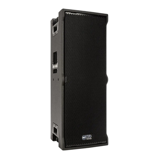
2. DESCRIPTION TTL 4-A / TTL C4-A - TTP 4-A / TTP C4-A - TTW 4-A / TTW C4-A The TTx 4-A and TTx C4-A modules deliver top quality sound for demanding events indoors or outdoors, and for small-to-medium sized areas� Their design provide the audio engineer with tonal balance and intelligibility while maintaining an unobtrusive and adaptable footprint�... -
Page 7: Rear Panel Features And Controls
When switched the RDNet setup is loaded and bypass any speaker local preset� RDNET IN/OUT PLUG SECTION The RDNET IN/OUT PLUG SECTION features etherCON connectors for the RCF RDNet protocol� This allows the user to completely control the speaker using the RDNet software� PRESET LABEL AC INPUT Powercon locking 3-pole AC mains�... -
Page 8: Connection
RCF SERVICE CENTRE before connecting the speaker� This fast check will avoid any damage� In case of need of changing the voltage please call your vendor or authorized RCF SERVICE CENTRE� This operation requires the replacement of the fuse value and is reserved to an RCF SERVICE CENTRE�... -
Page 9: Part 1 Ttl 4-A, Ttp 4-A, Ttw 4-A
PART 1 TTL 4-A, TTP 4-A, TTW 4-A TTL 4-A TTP 4-A TTW 4-A... -
Page 10: Presets
TTL 4-A, TTP 4-A, TTW 4-A IMPORTANT NOTE: The following presets are valid for TTL 4-A, TTP 4-A and TTW 4-A only. L1 - LINEAR Is the totally linear preset� The speaker curve response is perfectly linear� It is ideal when listening outdoor or in low reverberation rooms, at medium distance and at a medium or high sound pressure level�... -
Page 11: Floor Configurations
PART 1 | 6. FLOOR CONFIGURATIONS TTL 4-A, TTP 4-A, TTW 4-A IMPORTANT NOTE: The following configurations are valid for TTL 4-A, TTP 4-A and TTW 4-A only. 60° - 80° POLE SUBWOOFER COUPLED SPEAKERS MOUNTED MOUNTED OVER A SUBWOOFER... -
Page 12: Suspended Configurations
IMPORTANT NOTE: The following configurations are valid for TTL 4-A, TTP 4-A and TTW 4-A only. SINGLE SUSPENSION ON VERTICAL FLYBAR This configuration is suggested for TTL 4-A, TTP 4-A and TTW 4-A. The speakers can be suspended with the vertical flybar (FL-B V TT 4) indifferently with the horn in upper or lower position�... - Page 13 PART 1 | 7. SUSPENDED CONFIGURATIONS TTL 4-A, TTP 4-A, TTW 4-A The bracket locks itself in two positions as shown in the pictures: POSITION “1”, for a line array cluster configuration (horizontal) and POSITION “2”, for a sound column cluster configuration (vertical) POSITION ”1”...
- Page 14 PART 1 | 7. SUSPENDED CONFIGURATIONS TTL 4-A, TTP 4-A, TTW 4-A PREPARING THE FLYBAR It is possible to place the tube on the flybar in two different positions as shown in the pictures� FRONT FRONT Refferring to the “FRONT” and the letters indication, 4 different flybar configurations are obtainable:...
- Page 15 PART 1 | 7. SUSPENDED CONFIGURATIONS TTL 4-A, TTP 4-A, TTW 4-A WARNING! CAUTION! Always lock the tube on the flybar with the two pins pointed on the picture and secure them with the split pins on the other side.
- Page 16 PART 1 | 7. SUSPENDED CONFIGURATIONS TTL 4-A, TTP 4-A, TTW 4-A LINKING THE FLYBAR TO THE SPEAKER On one side of the speaker lower the linking bracket and fix it to the speaker with the quick lock pin� On the other side of the speaker raise the linking bracket and fix it to the flybar with the quick lock pin�...
- Page 17 DOUBLE SUSPENSION ON VERTICAL FLYBAR This configuration is suggested for TTL 4-A and TTP 4-A; not suggested with TTW 4-A. Two linked speakers can be suspended on the vertical flybar (FL-B V TT 4)� The speakers must be positioned with their horns side by side and linked together with the linking brackets�...
- Page 18 PART 1 | 7. SUSPENDED CONFIGURATIONS TTL 4-A, TTP 4-A, TTW 4-A Follow the instructions on PART 7�1 to link the first speaker to the flybar� On one side of the speaker lower the linking bracket and fix it to the speaker with the quick lock pin�...
- Page 19 WALL MOUNTING This configuration is suggested for TTL 4-A, TTP 4-A and TTW 4-A. The speakers can be mounted on a wall with the vertical bracket V-BR TT 4� Unscrew the four M8 lateral screws from the speaker, position the bracket and screw it to the speaker with the same M8 screws as shown in the image (place the bracket exactly as shown in the image)�...
- Page 20 PART 1 | 7. SUSPENDED CONFIGURATIONS TTL 4-A, TTP 4-A, TTW 4-A Now define the inclination angle and fix the speaker with the M6 screws provided, then clamp the M10 screws completely� POSITIVE VALUES NEGATIVES VALUES ARE FOR TILTING UPWARDS ARE FOR TILTING DOWNWARDS +30°...
-
Page 21: Part 2 Ttl C4-A, Ttp C4-A, Ttw C4-A
PART 2 TTL C4-A, TTP C4-A, TTW C4-A TTL C4-A TTP C4-A TTW C4-A... -
Page 22: Presets
TTL C4-A, TTP C4-A, TTW C4-A IMPORTANT NOTE: The following presets are valid for TTL C4-A, TTP C4-A and TTW C4-A only. Since TTx C4-A speakers are studied to be used in clusters, the usual RCF line array preset management is considered� LOW FREQUENCY PRESET... -
Page 23: Suspended Configurations
PART 2 | 9. SUSPENDED CONFIGURATIONS TTL C4-A, TTP C4-A, TTW C4-A PREPARING THE FLYBAR Referring to indications A, B, C on the flybar for positioning the tube on the hole A B C LINK POINT, it is possible to set the Flybar in 3 different configurations�... - Page 24 PART 2 | 9. SUSPENDED CONFIGURATIONS TTL C4-A, TTP C4-A, TTW C4-A LINKING THE FLYBAR TO THE SPEAKER (HORIZONTAL CONFIGURATION) Place the Flybar over the speaker by matching the two lateral brackets, then insert the quick lock pin on both sides� 9.1 LINKING TWO OR MORE SPEAKERS TOGETHER (HORIZONTAL CONFIGURATION) To link two or more speakers together in horizontal configuration, raise the lateral bracket on one speaker and insert it to the corresponding seat on the other speaker;...
- Page 25 IMPORTANT NOTE: RCF highly reccommends to chek on Easy Focus Software to verify if your configuration is appropriate for your application. To link the LINK BAR FL-B LINK TT4 to the speakers, simply proceed like linking two speakers: raise the lateral bracket on one speaker and insert it to the corresponding seat on the LINK BAR;...
- Page 26 TTL C4-A or TTP C4-A only� With this configuration the tube on the flybar must always be on central position (configuration B)� IMPORTANT NOTE: RCF highly reccommends to chek on Easy Focus Software to verify if your configuration is appropriate for your application.
- Page 27 PART 2 | 9. SUSPENDED CONFIGURATIONS TTL C4-A, TTP C4-A, TTW C4-A LIFTING BRACKET HORIZ. H-PLATE TT4 With the accessory LIFTING BRACKET HORIZ� H-PLATE TT4 it is possibile to suspend 2 or 3 TTL C4-A or TTP C4-A linked vertically side by side� LINKING 2 SPEAKERS FOR VERTICAL SUSPENSION Place two TTL C4-A or TTP C4-A side by side and link them together by lowering the two lateral brackets (upper and lower) and securing them with the quick lock pin�...
- Page 28 PART 2 | 9. SUSPENDED CONFIGURATIONS TTL C4-A, TTP C4-A, TTW C4-A On the bottom side, partially extract two quick lock pins (one from the central speaker and one from one of the speakrs beside), enough to free the front side of their seat� Then place the bottom plate on its seat and secure it by pushing back the quick lock pins all the way through� This is the hanging point to use in the 2 speakers configuration The 2-speakers vertical configuration is now set and ready to be suspended�...
- Page 29 PART 2 | 9. SUSPENDED CONFIGURATIONS TTL C4-A, TTP C4-A, TTW C4-A LINKING 3 SPEAKERS FOR VERTICAL SUSPENSION To suspend three speakers (TTL C4-A or TTP C4-A) with the LIFTING BRACKET HORIZ. H-PLATE TT4, you need to prepare the bracket by adding the two extension plates to the main bracket, as shown in the image�...
- Page 30 PART 2 | 9. SUSPENDED CONFIGURATIONS TTL C4-A, TTP C4-A, TTW C4-A Unscrew the two M10 bolts on top of each speaker (six total) and place the H-PLATE over the central speaker� Screw back the six M10 bolts (and washers) to secure the bracket to the speakers�...
- Page 31 PART 2 | 9. SUSPENDED CONFIGURATIONS TTL C4-A, TTP C4-A, TTW C4-A On the bottom side, partially extract both quick lock pins, enough to free the front side of their seat� Then place the bottom plate on its seat and secure it by pushing back the quick lock pins all the way through� This is the hanging point to use in the 3 speakers configuration The 3-speakers vertical configuration is now set and ready to be suspended�...
-
Page 32: Troubleshooting
10. TROUBLESHOOTING THE SPEAKER DOESN’T TURN ON Make sure the speaker is switched on and connected to an active AC power THE SPEAKER IS CONNECTED TO AN ACTIVE AC POWER BUT DOESN’T TURN ON Make sure the power cable is intact and connected correctly� THE SPEAKER IS ON BUT DOESN’T MAKE ANY SOUND Check if the signal source is sending correctly and if the signal cables are not damaged�... -
Page 34: Avvertenze Per La Sicurezza E Informazioni Generali
è diverso da persona a persona di sicurezza� RCF S�p�A� non si assume alcuna responsabilità per l’installazione e / o l’uso e dipende dalla durata dell’esposizione� Per prevenire un’esposizione potenzialmente errati di questo prodotto�... - Page 35 ATTENZIONE! CAUTELA! Per i diffusori alimentati, eseguire la pulizia solo quando l’alimentazione è spenta. RCF S.p.A. si riserva il diritto di apportare modifiche senza preavviso per rettificare eventuali errori e/o omissioni. Fare sempre riferimento all’ultima versione del...
-
Page 36: Descrizione
2. DESCRIZIONE TTL 4-A / TTL C4-A - TTP 4-A / TTP C4-A - TTW 4-A / TTW C4-A I diffusori TTx 4-A e TTx C4-A offrono un suono di alta qualità per eventi di grande spessore al chiuso o all’aperto e per aree di piccole e medie dimensioni�... -
Page 37: Pannello Posteriore - Funzioni E Controlli
SEZIONE RDNET IN/OUT PLUG. La SEZIONE RDNET IN/OUT PLUG presenta due prese per connettori etherCON per l’interfaccia con il protocollo RDNet� Questo permette all’utente di controllare il diffusore tramite l’utlizzo del software RCF RDNet� AC INPUT. Connettore di alimentazione Powercon per cavo di rete�... -
Page 38: Connessioni
(115 Volt o 230 Volt)� L’etichetta indica la giusta tensione� Se è indicato un voltaggio errato o se non è possibile localizzare l’etichetta, chiamare il proprio rivenditore o il CENTRO DI ASSISTENZA RCF autorizzato prima di collegare il diffusore� Questo rapido controllo eviterà... -
Page 39: Parte 1 Ttl 4-A, Ttp 4-A, Ttw 4-A
PARTE 1 TTL 4-A, TTP 4-A, TTW 4-A TTL 4-A TTP 4-A TTW 4-A... -
Page 40: Presets
TTL 4-A, TTP 4-A, TTW 4-A NOTA: I seguenti preset sono validi solo per TTL 4-A, TTP 4-A e TTW 4-A. L1. LINEAR. È un preset totalmente lineare� La curva di risposta del diffusore è perfettamente lineare� È ideale per gli aScolti all’aperto o in ambienti poco riverberanti, a media distanza ed a medi od alti livelli di volume�... -
Page 41: Configurazioni A Terra
PARTE 1 | 6. CONFIGURAZIONI A TERRA TTL 4-A, TTP 4-A, TTW 4-A NOTA: Le seguenti configurazioni sono valide solo per TTL 4-A, TTP 4-A e TTW 4-A. 60° - 80° MONTAGGIO SU COPPIA DI DIFFUSORI MONTAGGIO SU SUBWOOFER SU SUBWOOFER... -
Page 42: Configurazioni In Sospensione
NOTA: Le seguenti configurazioni sono valide solo per TTL 4-A, TTP 4-A e TTW 4-A. SOSPENSIONE SINGOLA CON FLYBAR VERTICALE Questa configurazione è consigliata per TTL 4-A, TTP 4-A e TTW 4-A. Questi diffusori possono essere sospesi con flybar verticale (FL-B V TT 4) sia orientati con la tromba in alto che in basso�... - Page 43 PARTE 1 | 7. CONFIGURAZIONI IN SOSPENSIONE TTL 4-A, TTP 4-A, TTW 4-A La staffa si blocca in due posizioni come mostrato nelle immagini: POSIZIONE “1”, per le configurazioni cluster line array (orizzontale) e POSIZIONE “2”, per una configurazione in cluster a colonna sonora (verticale) POSITION ”1”...
- Page 44 PARTE 1 | 7. CONFIGURAZIONI IN SOSPENSIONE TTL 4-A, TTP 4-A, TTW 4-A PREPARAZIONE DEL FLYBAR È possibile posizionare il tubo sul Flybar in due diverse posizione, così come mostrato nell’immagine� FRONT FRONT Facendo riferimento alla scritta “FRONT” e all’indicazione delle lettere, si possono ottenere 4 diverse configurazioni:...
- Page 45 PARTE 1 | 7. CONFIGURAZIONI IN SOSPENSIONE TTL 4-A, TTP 4-A, TTW 4-A ATTENZIONE! CAUTELA! Bloccare sempre il tubo sul flybar con i due perni indicati in figura e fissarli con le copiglie sull’altro lato. A seconda dell’orientamento del diffusore (con la tromba sul lato superiore o inferiore) posizionare il flybar sul diffusore e fissare le due staffe di...
- Page 46 PARTE 1 | 7. CONFIGURAZIONI IN SOSPENSIONE TTL 4-A, TTP 4-A, TTW 4-A COLLEGAMENTO DEL FLYBAR AL DIFFUSORE Su un lato del diffusore abbassare la staffa di collegamento e fissarla sul diffusore tramite un quick lock pin� Dall’altra parte del diffusore alzare la staffa di collegamento a fissarla al flybar con un quick lock pin�...
- Page 47 SOSPENSIONE DOPPIA CON FLYBAR VERTICALE Questa configurazione è cosigliata per TTL 4-A e TTP 4-A; non è consigliata per il modello TTW 4-A. Due diffusori collegati tra loro possono essere sospesi con flybar verticale (FL-B V TT 4)� I diffusori devono essere posizionati con le trombe affiancate e collegati tra loro con le staffe di collegamento�...
- Page 48 PARTE 1 | 7. CONFIGURAZIONI IN SOSPENSIONE TTL 4-A, TTP 4-A, TTW 4-A Seguire le istruzioni al punto 7�1 per collegare il primo diffusore al flybar� Su un lato del diffusore abbassare la staffa di collegamento e fissarla al diffusore con un quick lock pin�...
- Page 49 MONTAGGIO A MURO Questa configurazione è consigliata per TTL 4-A, TTP 4-A e TTW 4-A� I diffusori possono essere montati a parete con la staffa verticale V-BR TT 4� Svitare le quattro viti laterali M8 dal diffusore, posizionare la staffa e avvitarla all’altoparlante con le stesse viti M8 come mostrato nell’immagine (posizionare la staffa esattamente come mostrato nell’immagine)�...
- Page 50 PARTE 1 | 7. CONFIGURAZIONI IN SOSPENSIONE TTL 4-A, TTP 4-A, TTW 4-A Ora definire un angolo di inclinazione e fissare il diffusore mediante le viti M6 in dotazione, dopodichè serrare completamente le viti M10� VALORI POSITIVI INDICANO VALORI NEGATIVI INDICANO L’INCLINAZIONE VERSO L’ALTO...
-
Page 51: Parte 2 Ttl C4-A, Ttp C4-A, Ttw C4-A
PARTE 2 TTL C4-A, TTP C4-A, TTW C4-A TTL C4-A TTP C4-A TTW C4-A... -
Page 52: Presets
NOTA: I seguenti preset sono validi solo per TTL C4-A, TTP C4-A e TTW C4-A. Poiché i diffusori TTx C4-A sono studiati per essere utilizzati in cluster, viene considerata la consueta gestione dei preset di line array RCF� PRESET DELLE BASSE FREQUENZE Nella gamma delle basse frequenze l’interazione tra il suono dei singoli cabinet produce un... -
Page 53: Configurazioni In Sospensione
PARTE 2 | 9. CONFIGURAZIONI IN SOSPENSIONE TTL C4-A, TTP C4-A, TTW C4-A PREPARAZIONE DEL FLYBAR Facendo riferimento alle indicazioni A, B, C sul flybar per il posizionamento del tubo sul foro A B C LINK POINT, è possibile impostare il Flybar in 3 diverse configurazioni�... - Page 54 PARTE 2 | 9. CONFIGURAZIONI IN SOSPENSIONE TTL C4-A, TTP C4-A, TTW C4-A COLLEGAMENTO DEL DIFFUSORE AL FLYBAR (CONFIGURAZIONE ORIZZONTALE) Posizionare il Flybar sul diffusore facendo in modo che le due staffe laterali del flybar si inseriscano nelle sedi corrispondenti sul diffusore, dopodichè...
- Page 55 è un TTW C4-A� essere o un TTL C4-A o un TTP C4-A� NOTA: RCF consiglia vivamente di controllare il software Easy Focus per verificare se la configurazione è appropriata per la propria applicazione. Per installare l’accessorio LINK BAR FL-B LINK TT4 al diffusore, procedere come per collegare due diffusori: sollevare la staffa laterale sul diffusore a inserirla nella sede corrispondente sulla LINK BAR;...
- Page 56 TTL C4-A o TTP C4-A� Con questa configurazione il tubo del flybar deve sempre essere in posizione centrale (configurazione B)� NOTA: RCF consiglia vivamente di controllare il software Easy Focus per verificare se la configurazione è appropriata per la propria applicazione.
- Page 57 PARTE 2 | 9. CONFIGURAZIONI IN SOSPENSIONE TTL C4-A, TTP C4-A, TTW C4-A LIFTING BRACKET HORIZ. H-PLATE TT4 Con l’accessorio LIFTING BRACKET HORIZ� H-PLATE TT4 è possibile sospendere 2 o 3 TTL C4-A o TTP C4-A collegante verticalmente una a fianco all’altra�...
- Page 58 PARTE 2 | 9. CONFIGURAZIONI IN SOSPENSIONE TTL C4-A, TTP C4-A, TTW C4-A Sul lato inferiore, estrarre parzialmente i due quick lock pin (uno dal diffusore centrale e uno da uno dei diffusori a lato), quanto basta per liberare la parte anteriore della loro sede� Quindi posizionare la piastra inferiore sulla sua sede e fissarla rimettendo i quick lock pin nella loro posizione� Questo è...
- Page 59 PARTE 2 | 9. CONFIGURAZIONI IN SOSPENSIONE TTL C4-A, TTP C4-A, TTW C4-A COLLEGAMENTO DI 3 DIFFUSORI PER LA SOSPENSIONE VERTICALE Per sospendere tre diffusori (TTL C4-A o TTP C4-A) con l’accessorio LIFTING BRACKET HORIZ. H-PLATE TT4, è necessario preparare la staffa aggiungendo due piastre di estensione sulla staffa principale, come mostrato nell’immagine�...
- Page 60 PARTE 2 | 9. CONFIGURAZIONI IN SOSPENSIONE TTL C4-A, TTP C4-A, TTW C4-A Svitare i due bulloni M10 sopra ogni diffusore (sei in totale) e posizionare l’H-PLATE sul diffusore centrale� Riavvitare i sei bulloni M10 (e le rondelle) per fissare la staffa ai diffusori�...
- Page 61 PARTE 2 | 9. CONFIGURAZIONI IN SOSPENSIONE TTL C4-A, TTP C4-A, TTW C4-A Sul lato inferiore estrarre parzialmente entrambi i quick lock pin, quanto basta per liberare la parte anteriore della loro sede� Quindi posizionare la piastra inferiore sulla sua sede e fissarla spingendo i quick lock pin nella loro sede� Questo è...
-
Page 62: Risoluzione Dei Problemi
10. RISOLUZIONE DEI PROBLEMI IL DIFFUSORE NON SI ACCENDE Assicurarsi che il diffusore sia acceso e collegato a un’alimentazione attiva� IL DIFFUSORE È COLLEGATO A UN’ALIMENTAZIONE ATTIVA MA NON SI ACCENDE Verificare che il cavo di alimentazione sia integro e collegato correttamente� IL DIFFUSORE È... -
Page 64: Dimensions
DIMENSIONS The following dimensions are valid for all the six models of TTx 4-A and TTx C4-A. Le seguenti dimensioni sono valide per tutti e sei i modelli di TTx 4-A e TTx C4-A. -
Page 65: Specifications
Frequency Response: 45 Hz ÷ 20000 Hz Max SPL @ 1m: 135 dB Coverage angle: 100°H x 25°V (TTL 4-A; TTL C4-A) 600°H x 25°V (TTP 4-A; TTP C4-A) 100°H x 50°V (TTW 4-A; TTW C4-A) Transducers Compression Driver: 1 x 1.5'' neo, 4.0'' v.c Woofer: 2 x 10'' neo, 3.0'' v.c... - Page 66 10307652 RevE RCF S.p.A. Via Raffaello Sanzio, 13 - 42124 Reggio Emilia - Italy Tel +39 0522 274 411 - Fax +39 0522 232 428 - e-mail: info@rcf�it - www.rcf.it...
Need help?
Do you have a question about the TTL 4-A and is the answer not in the manual?
Questions and answers