Advertisement
Available languages
Available languages
Quick Links
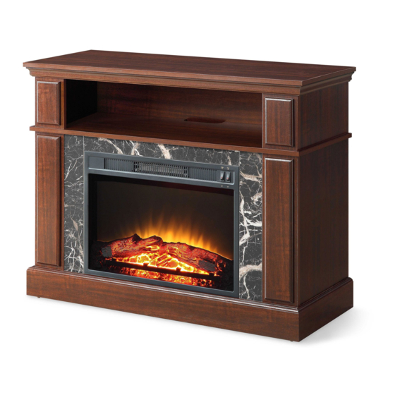
Media Fireplace Console
Stock # WMFP41EC-3
If you have any questions regarding assembly or if parts are missing, DO NOT return this item to the
store where it was purchased. Please call our customer service number and have your instructions
and parts list ready to provide the model name, part name or factory number:
Pacific Standard Time: 8:30 a.m. - 4:30 p.m., Monday - Friday
Or visit our web site 24 hours a day, 7 days a week for product assistance at
Or e-mail your request to parts@whalenfurniture.com
THIS INSTRUCTION BOOKLET CONTAINS IMPORTANT SAFETY INFORMATION.
PLEASE READ AND KEEP FOR FUTURE REFERENCE.
# MS18-D4-1011-01 White Finish
ADULT ASSEMBLY REQUIRED
866-942-5362
www.whalenstyle.com
Date 2020-07-18
LOT NUMBER:
DATE PURCHASED:
Cherry Finish
Rev. 0001-B
/
/
Advertisement

Subscribe to Our Youtube Channel
Related Manuals for Mainstays WMFP41EC-3


Summary of Contents for Mainstays WMFP41EC-3
- Page 1 LOT NUMBER: DATE PURCHASED: Media Fireplace Console Stock # WMFP41EC-3 Cherry Finish # MS18-D4-1011-01 White Finish ADULT ASSEMBLY REQUIRED If you have any questions regarding assembly or if parts are missing, DO NOT return this item to the store where it was purchased. Please call our customer service number and have your instructions...
- Page 2 M A X I M U M R E C O M M E N D E D W E I G H T L O A D S MANUFACTURER: Whalen Furniture Manufacturing CATALOG: Media Fireplace Console MODEL # WMFP41EC-3 / MS18-D4-1011-01 FITS UP TO MOST 48” DIAGONAL FLAT PANEL TVs MAXIMUM LOAD 50 lb.
- Page 3 IMPORTANT Before you begin: Open, identify and count all parts prior to assembly. Lay out parts on a flat and non- abrasive surface. You will need the parts identified on page 4 and 5 of this instruction manual. NOTE: IT IS VERY IMPORTANT TO USE GLUE WITH DOWELS. EXCESS GLUE CAN BE WIPED OFF WITH DAMP CLOTH.
-
Page 4: Parts And Hardware List
Parts and Hardware List Please read completely through the instructions and verify that all listed parts and hardware are present before beginning assembly. A- Top Panel (Qty. 1) B- Left Upper Side Panel (Qty.1) C- Right Upper Side Panel (Qty. 1) D- Left Upper Front Panel (Qty. - Page 5 Parts and Hardware List Please read completely through the instructions and verify that all listed parts and hardware are present before beginning assembly. (1) Cam Lock (2) Cam Bolt (3) M8 x 30 mm Wood Dowel (Qty. 27+1 extra) (Qty. 27+1 extra) (Qty.
- Page 6 Assembly Instructions ② x 27 1. Unpack the unit and confirm that you have all the hardware and required parts. Assemble the unit on a carpeted floor or the empty carton to avoid any scratch. 2. Locate the Top Panel (A), Center Shelf (F), Upper Front Panels (D and E) and Lower Front Panels (I and J) with the holes facing up.
- Page 7 Assembly Instructions ① x 4 ③ x 2 3. Insert one Wood Dowel (3) into the center end hole of Left Upper Side Panel (B). Tap it in with a rubber mallet, if necessary. Make sure that you use a small amount of glue with both ends of all dowels. 4.
- Page 8 Assembly Instructions ① x 6 ③ x 4 6. Repeat the same procedure to combine the Left Lower Front and Side Panels (I and G), Right Lower Front and Side Panels (J and H) together.
- Page 9 Assembly Instructions ③ x 2 ① x 3 7. Align and attach the Center Crossbar (K) to the Center Shelf (F) by using two Wood Dowels (3) and three Cam Locks (1).
- Page 10 Assembly Instructions ③ x 6 ① x 6 8. Insert six Wood Dowels (3) into the drilled holes on the assembled Upper Panels (B, C, D and E) and attach them to the Top Panel (A) by engaging six Cam Locks (1).
- Page 11 Assembly Instructions ③ x 4 ⑤ x 6 9. Insert four Wood Dowels (3) into the inner holes at the bottom of both Upper Side Panels (B and C). 10. Properly position the Center Shelf (F) onto the inserted Wood Dowels (3). Insert six 38 mm Screws (5) through the countersunk holes on the Center Shelf (F) and screw into the Upper Panels (B, C, D and E).
- Page 12 Assembly Instructions ③ x 4 ① x 8 11. Insert four Wood Dowels (3) into the top inner holes of both Lower Side Panels (G and H). 12. Align the large holes on Center Shelf (F) with the inserted Wood Dowels (3) on the Lower Side Panels and press them together.
- Page 13 Assembly Instructions ③ x 6 ⑤ x 8 13. Align and attach the Base (L) to the previous assembly with six Wood Dowels (3) and eight 38 mm Screws (5).
- Page 14 Assembly Instructions I /J ④ x 4 14. Stand the assembled unit upright. 15. With the pilot holes as a guide, fasten the Center Crossbar (K) to the Lower Front Panels (I and J) by attaching two Metal Brackets (8) at the joints, using two 12 mm Screws (4) per bracket.
- Page 15 Assembly Instructions ⑥ x 16 16. Now, go back and securely tighten all the Cam Locks and the Screws. Make sure that all the parts are tight and there are no gaps between the parts. This will help keep the unit square. 17.
- Page 16 Assembly Instructions 18. Unpack the fireplace insert from the inner box and follow the instructions to install the Top Trim and Side Trims to the fireplace insert. 19. Lift the fireplace insert carefully into the back of the assembled mantel and center it in the opening. drag the insert across the Base (L) as it may scratch the unit.
- Page 17 Assembly Instructions NOTE: To prevent your TV from tipping, you must install the Strip Stopper if you place your flat panel television directly on the console. Otherwise, skip to step 21. 20. Remove the paper backing from the Stop Rail (N), then properly align the Stop Rail with the top edge of the stopper template on Top Panel (A).
- Page 18 Assembly Instructions Tools required (not provided): Phillips screwdriver, stud finder, tape measure, pencil, power drill and 1/8’’ drill bit. 23. Ask for assistance to position the assembled mantel at the desired location against a wall. 24. Now, follow the instructions printed on the plastic bag containing the Tipping Restraint Hardware to attach the tip-over restraints to the unit and the wall, as shown in the illustration.
-
Page 19: Care And Maintenance
Care and Maintenance Use a soft, clean cloth that will not scratch the surface when dusting. Use of furniture polish is not necessary. Should you choose to use polish, test first in an inconspicuous area. Using solvents of any kind on your furniture may damage your furniture’s finish. ... - Page 21 LOTE NÚMERO: FECHA COMPRA: Consola para medios con chimenea Acabado Cereza Serie # WMFP41EC-3 Acabado Blanco # MS18-D4-1011-01 ENSAMBLE REQUERIDO POR ADULTO Si tiene alguna pregunta acerca del ensamble o si le hace falta alguna parte, no devuelva est é producto a la tienda donde lo compro .
- Page 22 PESOS MÁXIMOS RECOMENDADOS FABRICANTE: Whalen Furniture Manufacturing CATÁLOGO: Consola para medios con chimenea MODELO # WMFP41EC-3 / MS18-D4-1011-01 PARA MAYORÍA DE LAS TELEVISIONES DE PANTALLA PLANA DE 48” CARGA MÁXIMA 50 lb. (22.7 kg) POSICIONE LA TELEVISIÓN ATRÁS CARGA MÁXIMA 50 lb. (22.7 kg) ESTA UNIDAD NO DEBE UTILIZARSE CON TELEVISIONES CRT O DE TUBO.
- Page 23 IMPORTANTE Antes de comenzar: Abra, identifique y cuente todas las partes antes del ensamble. Coloque las piezas sobre una superficie plana y no abrasiva. Tendrá que las partes identificadas en la página 4 y 5 de este manual de instrucciones. NOTA: ES MUY IMPORTANTE PARA EL USO DE GOMA CON LOS PERNSO DE MADERA.
- Page 24 Partes y lista de material de ferretería. Por favor, lea completamente las instrucciones y verifique que todas las partes y material de ferretería enumerados están presentes antes de comenzar el ensamble. A- Panel superior (Cant. 1) B- Lado izquierdo superior (Cant. 1) C- Lado derecho superior (Cant. 1) D- Panel izquierdo frontal sup.
- Page 25 Partes y lista de material de ferretería. Por favor, lea completamente las instrucciones y verifique que todas las partes y material de ferretería enumerados están presentes antes de comenzar el ensamble. (1) Tuerca de fijación (2) Tornillo de fijación (3) Perno de madera de M8 x 30 mm (Cant.
-
Page 26: Instrucciones De Ensamble
Instrucciones de ensamble ② x 27 1. Desempaque la unidad y confirmar que usted tiene todo el material de ferretería y piezas necesarias. Ensamble la unidad en un lugar o de la caja de cartón vacía para evitar cualquier rasguños. 2. - Page 27 Instrucciones de ensamble ① x 4 ③ x 2 3. Inserte un perno de madera (3) en el orificio extremo centro superior izquierdo del panel lateral (B). Golpee con un mazo de goma, si es necesario. Asegúrese de que utiliza una pequeña cantidad de pegamento con los dos extremos de los pernos.
- Page 28 Instrucciones de ensamble ① x 6 ③ x 4 6. Repita el mismo procedimiento para combinar los paneles inferiores (I y G), y paneles frontales inferiores (J y H).
- Page 29 Instrucciones de ensamble ③ x 2 ① x 3 7. Alinear y unir el soporte central (K) para la repisa central (F) mediante el uso de dos pernos de madera (3) y tres tuercas de fijación (1).
- Page 30 Instrucciones de ensamble ③ x 6 ① x 6 8. Insertar seis pernos de madera (3) en los agujeros perforados en los paneles superiores (B, C, D y E) y fijar al panel superior (A) con seis tuercas de fijación (1).
- Page 31 Instrucciones de ensamble ③ x 4 ⑤ x 6 9. Insertar cuatro pernos de madera (3) en los agujeros grandes de los paneles superiores (B y C). 10. Colocar adecuadamente la repisa central (F) sobre los pernos de madera insertados (3). Inserte seis tornillos de 38 mm (5) a través de los agujeros avellanados en la repisa central (F) y fije en los paneles superiores (B, C, D y E).
- Page 32 Instrucciones de ensamble ③ x 4 ① x 8 11. Insertar cuatro pernos de madera (3) en los agujeros grandes de los paneles inferiores y frontales (G y H). 12. Alinear los agujeros grandes en la repisa central (F) con los pernos de madera insertados (3) en los paneles inferiores y pulse juntos.
- Page 33 Instrucciones de ensamble ③ x 6 ⑤ x 8 13. Alinear y adjuntar la base (L) al último ensamble con seis pernos de madera (3) y ocho tornillos de 38 mm (5).
- Page 34 Instrucciones de ensamble I /J ④ x 4 14. Poner la unidad en posición vertical. 15. Con los agujeros piloto como una guía, sujete el soporte central (K) para los paneles frontales inferiores (I y J) uniendo dos soportes metálicos (8) en las articulaciones, utilizando dos tornillos de 12 mm (4) por soporte.
- Page 35 Instrucciones de ensamble ⑥ x 16 16. Ahora, volver atrás y apriete firmemente todas las tuercas de fijación y los tornillos. Asegúrese de que todas las piezas estén apretadas y no hay espacios entre las partes. Esto ayudará a mantener la unidad escuadra. 17.
- Page 36 Instrucciones de ensamble 18. Saque el inserto de chimenea y siga las instrucciones para instalar las moldura superior y lateral al inserto de chimenea. Levante el inserto de la chimenea cuidadosamente en la parte posterior de la repisa ensamblada y centrarla en la apertura.
- Page 37 Instrucciones de ensamble NOTA: Para prevenir que su TV se incline, debe instalar la tira tope si instala su TV plana sobre la consola. De lo contrario, vaya al paso 21. 20. Retire el papel protector del riel tope (N), y luego alinear correctamente al borde superior de la plantilla para tope en el panel superior (A).
- Page 38 Instrucciones de ensamble Herramientas requeridas (no incluidas): Desarmador estrella, localizador de barrotes, cinta métrica, lápiz, taladro y broca de 1/8”. 23. Pide ayuda para colocar la unidad ensamblada en el lugar deseado contra una pared. 24. Ahora, siga las instrucciones impresas en la bolsa de plástico que contiene el herraje de restricción de movimiento a la unidad y la pared, como se muestra en la ilustración.
-
Page 39: Mantenimiento Y Cuidados
Mantenimiento y Cuidados Use una toalla suave y limpia para evitar daños y rayones. Uso de cera para pulir muebles no es necesario. Si desea usar cera, pruebela en un área que no sea visible para revisar su funcionamiento. ...
Need help?
Do you have a question about the WMFP41EC-3 and is the answer not in the manual?
Questions and answers