Table of Contents
Advertisement
Advertisement
Table of Contents

Related Manuals for woodmizer LT40 MH Series

Summary of Contents for woodmizer LT40 MH Series
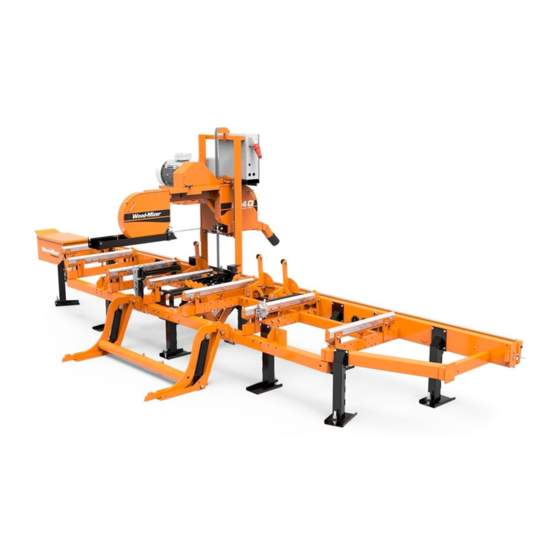
- Page 1 D42 Engine Safety, Operation, Maintenance & Parts Manual LT40 Series MH rev. E3.00 LT40 Series DH rev. E4.00 Safety is our #1 concern! Read and understand all safety information and instructions before oper- ating, setting up or maintaining this machine. February 1998 Form #916...
-
Page 2: Table Of Contents
Table of Contents Section-Page SECTION 1 OPERATION Starting The Engine................1-1 SECTION 2 MAINTENANCE Safety......................2-1 Cooling System ..................2-2 Fuel Filter ....................2-4 Battery ....................2-5 Alternator Belt ..................2-6 Radiator Fan Belt Adjustment ..............2-7 RPM Adjustments ..................2-8 SECTION 3 REPLACEMENT PARTS Fuel Tank....................3-1 Engine Mount Assembly ................3-2 Engine Assembly..................3-4 Primary Fuel Filter .................3-6 Throttle Assembly ..................3-7... - Page 3 ABOUT THIS MANUAL This manual is provided as a supplement to the equipment manufacturer’s manuals. This ® manual provides information specific to the use of this equipment on the Wood-Mizer sawmill. Refer to the sawmill operator’s manual and manufacturer's manual before attempting to operate this equipment.
-
Page 4: Operation
Operation Starting The Engine SECTION 1 OPERATION Starting The Engine Control Lights See Figure 1-1. The following indicator lights are located on the sawmill control panel. Alternator Charge Indicator: Lights up if the alternator is not charging the battery. Engine Temperature Indicator: Lights up if the engine is overheating. A circuit breaker assembly in the engine harness will shut the engine off if the engine overheats. - Page 5 Operation Starting The Engine Engine Start DANGER! Always be sure the blade is disengaged and all persons are out of the path of the blade before starting the engine. Failure to do so will result in serious injury. DANGER! Operate your engine/machine only in well venti- lated areas.
- Page 6 Operation Starting The Engine Engine Shutoff CAUTION! A minimum 2 minute idle time is recommended to allow the battery charge and the turbo-charger to cool down before the engine is shut off. Turn the key switch to the off (#0) position. doc062309 Operation...
-
Page 7: Maintenance
Maintenance Safety SECTION 2 MAINTENANCE Refer to the manufacturer’s manual for maintenance intervals and procedures unless oth- erwise instructed in this manual. Follow the manufacturer’s recommendations for dusty conditions. IMPORTANT! This manual only provides information about additional procedures or procedures to be performed at dif- ferent time intervals than found in the manufacturer's manu- als. -
Page 8: Cooling System
Maintenance Cooling System Cooling System Clean the radiator fins every 8 hours of operation. Spray the radiator with water from a hose or compressed air to clean sawdust from the radiator fins. Do not use a pressure sprayer. CAUTION! Failure to keep the radiator fins clear of sawdust and/or dirt may cause the engine to overheat resulting in damage to the engine. - Page 9 Maintenance Cooling System tilled water). 3h0963 FIG. 2-0 Maintenance doc110909...
-
Page 10: Fuel Filter
Maintenance Fuel Filter Fuel Filter See Figure 2-1. Replace the primary fuel filter cartridge every 1500 hours or one year of operation. After replacing the filter cartridge, loosen the air bleed screw and operate the 1500 fuel pump bail until fuel begins to flow from the valve and is free of air bubbles. Tighten the bleed screw. -
Page 11: Battery
Maintenance Battery Battery Check the battery electrolyte level every 50 hours of operation. See manufacturer’s man- ual for instructions. DANGER! Batteries expel explosive gases. Keep sparks, flames, burning cigarettes, or other ignition sources away at all times. Always wear safety goggles and a face shield when working near batteries. -
Page 12: Alternator Belt
Maintenance Alternator Belt Alternator Belt The belt tension should be checked after the first 100 hours of operation, when the bat- tery is not charging properly or when the alternator belt is squealing. If the battery contin- ues to not charge properly or the belt continues to squeal after the initial belt adjustment, replace the belt. -
Page 13: Radiator Fan Belt Adjustment
Maintenance Radiator Fan Belt Adjustment 6. After the alternator belt has been tensioned, tighten the adjustment bolt jam nut. Tighten the upper and lower pivots and replace the belt covers. Radiator Fan Belt Adjustment The fan belt tension should be checked after the first 100 hours of operation, when the engine is overheating or when the fan belt is squealing. -
Page 14: Rpm Adjustments
Maintenance RPM Adjustments RPM Adjustments WARNING! Remove the blade before performing any engine service. Failure to do so may result in serious injury. Check the RPM with a tachometer after the first 20 hours of operation and every 200 hours thereafter. High-end RPM should be 3200 RPM and low-end RPM should be 1500 RPM. - Page 15 Maintenance RPM Adjustments 2. Start the engine to measure the low-end RPM. Let idle for 10 minutes. 3. With the engine at idle, check the low-end RPM. Adjust to 1500. To decrease speed, loosen the idle adjustment screw. To increase speed, tighten the idle adjustment screw. See Figure 2-5.
- Page 16 Maintenance RPM Adjustments See Figure 2-6. Upper Throttle Cable Mount Mounting Bolts Bracket Throttle Cable Throttle Cable Housing 3H0748-12 FIG. 2-6 CAUTION! Failure to properly center the throttle cable in the cable housing may result in premature cable wear. 2-10 doc110909 Maintenance...
-
Page 17: Replacement Parts
Replacement Parts Fuel Tank SECTION 3 REPLACEMENT PARTS Fuel Tank 3H0780B DESCRIPTION Indicates Parts Available In Assemblies Only) PART # QTY. TANK ASSEMBLY, 5 GALLON GREEN DIESEL A12132 Tank, 5 Gallon Green Fuel P12166 Pickup, 9" Fuel P12172 Cap, 3/5 Gallon Fuel Tank P09683 Fitting, 1/4”... -
Page 18: Engine Mount Assembly
Replacement Parts Engine Mount Assembly Engine Mount Assembly DESCRIPTION Indicates Parts Available In Assemblies Only) PART # QTY. MOUNT WELDMENT, FRONT KUBOTA ENGINE 097154-1 MOUNT WELDMENT, REAR KUBOTA ENGINE 087945-1 VIBRATION ABSORBER, CLUTCH 090666-1 Bolt, M10X70-8.8 HEX HEAD, ZINC F81003-20 Washer, 3/8"... - Page 19 Replacement Parts Engine Mount Assembly BOLT M6x12-8.8-Fe/Zn5 F81001-7 WASHER, 10.2 SPLIT LOCK ZINC F81053-3 BOLT M10x1,25x25-8.8-A-Fe/Zn5 F81003-29 WASHER, 10.2 SPLIT LOCK ZINC F81055-2 BOLT, M8X45 - 8.8 HEX HEAD GRADE 5 F81002-14 WASHER, M8, FLAT ZINC F81054-1 Replacement Parts D33doc110909...
-
Page 20: Engine Assembly
Replacement Parts Engine Assembly Engine Assembly 3H0748-10 DESCRIPTION Indicates Parts Available In Assemblies Only) PART # QTY. ENGINE, D33 V1505-E3B-EU-XL1 100930 Belt, Kubota Fan 097739 Radiator Fan 097740 Filter, Kubota Fuel, Complete 090208 Filter, Kubota Oil 097743 Gasket Kit, Kubota Lower 097744 Gasket Kit, Kubota Upper 097745... - Page 21 Replacement Parts Engine Assembly Motor, Kubota Starter 097759 Plug, Kubota Oil Drain 097760 Pump, Kubota Fuel Injector 097761 Pump, Kubota Fuel Transfer 097762 Pump, Kubota Water 097763 Radiator Parts (See Section 3.8) Sending Unit, Kubota Heat Sensor 097764 Solenoid, Kubota Stop 097765 Switch, Kubota Oil Pressure 097766...
-
Page 22: Primary Fuel Filter
Replacement Parts Primary Fuel Filter Primary Fuel Filter 3H0459 DESCRIPTION Indicates Parts Available In Assemblies Only) PART # QTY. FILTER ASSEMBLY, FUEL 16616-43001(D52/184) 090208 FILTER ASSEMBLY, STANDADYNE FUEL FPV-5,7 04WP40/3 088101 Filter, Standadyne Fuel Cartridge #31865 015898 FITTING, 8MM, FILTR FPV-5,7 088094 HOSE, 5/16”... -
Page 23: Throttle Assembly
Replacement Parts Throttle Assembly Throttle Assembly 3H0748-4 DESCRIPTION Indicates Parts Available In Assemblies Only) PART # QTY. CABLE, KUBOTA THROTTLE 015857 Spring, Throttle 016033 BOLT, 5/16-18 X 3/4” HEX HEAD F05006-5 NUT, 5/16-18 HEX SELF-LOCKING F05010-20 BRACKET, LOWER THROTTLE CABLE MOUNT 015853 BOLT, M10-1.5 X 25MM HEX HEAD FULL THREAD GRADE 5 F05009-52... - Page 24 Replacement Parts Throttle Assembly BOSS, 1/4 X 1/2 X .26” AL-BRONZE 016339 WASHER, .25ID X .62OD X .06THK, PLATED 016175 NUT, 1/4-20 NYLON LOCK F05010-69 NUT, 1/4-20 NYLON LOCK F05010-69 NUT, 5/16-18 SELF-LOCKING HEX F05010-20 BOLT, 5/16-18 X 1 1/4” HEX HEAD FULL THREAD F05006-18 NUT, 5/16-18 HEX LOCK F05010-6...
-
Page 25: Muffler Assembly
Replacement Parts Muffler Assembly Muffler Assembly smpl04 DESCRIPTION Indicates Parts Available In Assemblies Only) PART # QTY. MUFFLER, KUBOTA ENGINE 092652 BOLT, M8X25-8.8 HEX HEAD ZINC F81002-5 WASHER, 8.2 ZINC SPLIT LOCK F81054-4 Replacement Parts D33doc110909... -
Page 26: Drive Assembly
Replacement Parts Drive Assembly Drive Assembly 3H0748-9B DESCRIPTION Indicates Parts Available In Assemblies Only) PART # QTY. SHAFT, KUBOTA POWER 087953 SHEAVE, 5V X 4.46” POLY V (GAS/DIESEL) 085921 BUSHING, E15 MOTOR ASSEMBLY 087066 BELT, 3BX72 DRIVE 014085 BRACKET, DRIVE BELT SUPPORT 087958 BOLT, 3/8-16 X 1”... -
Page 27: Radiator Assembly & D33 Engine Guards
Replacement Parts Radiator Assembly & D33 Engine Guards Radiator Assembly & D33 Engine Guards 13 14 3h0975 DESCRIPTION Indicates Parts Available In Assemblies Only) PART # QTY. RADIATOR, KUBOTA D33 ENGINE 097373 RADIATOR GUARD, KUBOTA D33 ENGINE 098486-1 BOLT M6X16 8.8 FE/ZN5 F81001-15 WASHER, M6 SPLIT LOCK ZINC F81053-3... - Page 28 Replacement Parts Radiator Assembly & D33 Engine Guards NUT, M6, HEX NYLON LOCK ZINC F81031-2 BRACKET, D33 KUBOTA RADIATOR, PTD 090767-1 RADIATOR JOINT, METAL-RUBBER 088183 NUT, M8, HEXAGON, NYLON LOCK ZINC F81032-2 BOLT, M10-1.5X25MM HH GR8.8 F81003-11 WASHER 10,5 SPLIT LOCK ZINC F81055-6 NUT, M10, NYLON HEX ZINC LOCK F81033-1...
-
Page 29: Alternator Assembly
Replacement Parts Alternator Assembly Alternator Assembly 13 14 3H0748-7C DESCRIPTION Indicates Parts Available In Assemblies Only) PART # QTY. WIRE ASSEMBLY, 61/140 AMP ALTERNATOR PLUG 015969 ALTERNATOR ASSEMBLY, 140 AMP 023730 Alternator, 140 Amp 023695 Pulley, 140 Amp Alternator 023694 BRACKET, ALTERNATOR SUPPORT 093215-1 WASHER, 10.5 SAE FLAT... - Page 30 Replacement Parts Alternator Assembly WASHER, 8.2 SPLIT LOCK F81054-4 WASHER, 8.4 FLAT F81054-1 WASHER, 10.2 SPLIT LOCK F81055-2 WASHER, 6.5 FLAT F81053-11 BOLT, M10 X 1.25 X 25MM HEX HEAD F81003-29 BELT, 6PK1080 FIBERGLASS ALTERNATOR 088181 GUARD WELDMENT, ALTERNATOR BELT 093470-1 BOLT, M6X12-8.8 HEX HEAD F81001-7...
-
Page 31: 3.10 Engine Pulley Guards
Replacement Parts Engine Pulley Guards 3.10 Engine Pulley Guards 3H0748-8C DESCRIPTION Indicates Parts Available In Assemblies Only) PART # QTY. GUARD WELDMENT, KUBOTA ENGINE PULLEY 095086-1 BOLT, M6x12-8.8 HEX HEAD F81001-7 WASHER, 6,5 ZINC F81053-11 DECAL, 3300 RPM ENGINE DIRECTION S20097B Includes in 099517 - LT40DC Pictographic Decal Kit. - Page 32 Replacement Parts Engine Pulley Guards 3-16 D33doc110909 Replacement Parts...
-
Page 33: Electrical Wiring Diagrams, D42
Electrical Information SECTION 4 ELECTRICAL WIRING DIAGRAMS, D42 IMPORTANT! When using a sawmill with the rewired con- trol panel it is very important not to switch between saw head forward/backward movement until the saw head stops. Failure to do so may result in serious sawmill dam- age. - Page 34 PCB1 BROWN Power Feed PCB VIOLET +12V SOL3 SOL2 SOL4 SOL5 SOL1 SW 10 Fwd/Rev Switch Up/Down Switch ENKODER MSK320 GND W1 Blade Guide Feed Rate Pot Switch Hourmeter Board Return FIG. 4-1 D42 CONTROL BOX DIAGRAM).
- Page 35 FIG. 4-4 D42 CONTROL BOX DIAGRAM (VARIABLE REVERS MOVEMENT SPEED).
- Page 36 H yd rau lic V alve Sw itc h SO L 8 SO L 9 C op per S trip P os itive C on tac t P ow er F eed B atte ry H ydraulic H yd raulic Mo tor M otor 1 M otor 2...
- Page 37 Component List It e m Mf g . P a r t N o . Mf g . Woo d -M iz e r De s c ri p t i o n Pa r t N o . 023 73 0 W o o d - M iz e r 0 23 73 0 A lter n a to r, 14 0 A m p...
Need help?
Do you have a question about the LT40 MH Series and is the answer not in the manual?
Questions and answers