Table of Contents
Advertisement
Quick Links
Advertisement
Chapters
Table of Contents

Related Manuals for 2N Telekomunikace LTE Verso


Summary of Contents for 2N Telekomunikace LTE Verso
- Page 1 Installation manual 2N® LTE Verso v.1.6 www.2n.com...
-
Page 2: Table Of Contents
Installation manual 2N® LTE Verso Content: • 1. Product Overview • 1.1 Components and Associated Products • 1.2 Terms and Symbols • 2. Description and Installation • 2.1 Before You Start • 2.2 Mechanical Installation • 2.2.1 One Module Box •... -
Page 3: Product Overview
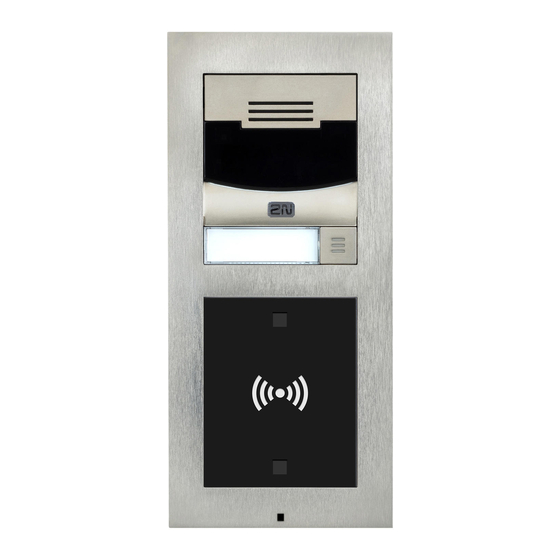
Basic Features ® LTE Verso is an elegant and reliable LTE intercom equipped with lots of useful functions, which are not quite common in this category of devices. A mobile LTE connection makes it possible to install devices where no LAN cable connection is available. The My2N portal helps make calls to mobile phones and appropriate 2N devices without complex configuration. - Page 4 ® LTE Verso installation – simply assemble the modules, insert a SIM card and connect a power supply. The modules are plug&play, so you do not have to configure them manually. The intercom is fed from a 12V power supply.
-
Page 5: Components And Associated Products
Installation manual 2N® LTE Verso 1.1 Components and Associated Products Main Units ® • Main unit LTE Verso • European LTE support only Part No. 9155401C- • HD camera • There may be just one main unit in every installation. The main... - Page 6 Installation manual 2N® LTE Verso ® • Main unit LTE Verso • European LTE support only Part • HD camera No. 9155401CB-E • There may be just one main unit in every installation. The main unit installation requires two frame/box positions one of which is left for additional installation of a module or internal antenna stuck to a plastic blind.
- Page 7 Installation manual 2N® LTE Verso Warning • Removing the stuck LTE antenna from the blind module and subsequent placement into another device part, under any card reader module, e.g., results in interference and deteriorated functionality of the whole device.
- Page 8 Installation manual 2N® LTE Verso Diagnostic device ® • LTE Verso – debug LAN module ® 2N Part. No. • used fot 2N LTE Verso troubleshooting and configuration 9155049 Axis Part No. 02284-001 Frames • Flush mounting frame, 1 module 2N Part No. 9155011...
- Page 9 Installation manual 2N® LTE Verso • Flush mounting frame, 1 module 2N Part No. 9155011B Axis Part No. 01279-001 • Flush mounting frame, 2 modules 2N Part No. 9155012 Axis Part No. 01280-001 9 / 213...
- Page 10 Installation manual 2N® LTE Verso • Flush mounting frame, 2 modules 2N Part No. 9155012B Axis Part No. 01281-001 10 / 213...
- Page 11 Installation manual 2N® LTE Verso • Flush mounting frame, 3 modules 2N Part No. 9155013 Axis Part No. 01282-001 11 / 213...
- Page 12 Installation manual 2N® LTE Verso • Flush mounting frame, 3 modules 2N Part No. 9155013B Axis Part No. 01283-001 • Surface mounting frame, 1 module 2N Part No. 9155021 Axis Part No. 01287-001 12 / 213...
- Page 13 Installation manual 2N® LTE Verso • Surface mounting frame, 1 module 2N Part No. 9155021B Axis Part No. 01288-001 • Surface mounting box, 2 modules 2N Part No. 9155022 Axis Part No. 01289-001 13 / 213...
- Page 14 Installation manual 2N® LTE Verso • Surface mounting box, 2 modules 2N Part No. 9155022B Axis Part No. 01290-001 14 / 213...
- Page 15 Installation manual 2N® LTE Verso • Surface mounting box, 3 modules 2N Part No. 9155023 Axis Part No. 01291-001 15 / 213...
- Page 16 Installation manual 2N® LTE Verso • Surface mounting box, 3 modules 2N Part No. 9155023B Axis Part No. 01292-001 • The 1-module frame is used when another module is added to the existing installation or when the module is mounted to an extended interconnecting cable for an outgoing reader, for example.
- Page 17 Installation manual 2N® LTE Verso Extending Modules ® • IP/LTE Verso – Infopanel • The Infopanel module helps you place such 2N Part No. 9155030 information into the intercom installation as house Axis Part. No. 01252-001 number, opening hours and similar data. The Infopanel backlight is software controlled.
- Page 18 The keypad digits and symbols are backlit. ® • IP/LTE Verso – RFID reader, 125 kHz • The card reader module provides you with access 2N Part No. 91550941 control via contactless cards or keyfobs. The module supports the 125 kHz EM4xxx cards.
- Page 19 Installation manual 2N® LTE Verso ® • IP/LTE Verso – Touch keypad & RFID reader 125kHz, 13.56MHz, NFC 2N Part No. 9155081 • The touch keypad and card reader module provides Axis Part No. 01636-001 you with access control via contactless cards or keyfobs.
- Page 20 Installation manual 2N® LTE Verso ® • IP/LTE Verso – Touch keypad & RFID reader 125kHz, secured 13.56MHz, NFC 2N Part No. 9155083 • The touch keypad card reader module provides you Axis Part No. 01638-001 with access control via contactless cards or keyfobs.
- Page 21 Installation manual 2N® LTE Verso ® IP/LTE external Bluetooth reader (USB interface) 2N Part No. 9137422E An external Bluetooth reader connecting to your computer via USB. Axis Part No. 01402-001 It can be used to pair new users who want to use their ®...
- Page 22 Installation manual 2N® LTE Verso ® • IP/LTE Verso – 5 buttons • A module with 5 mechanical quick dial buttons. The 2N Part No. 9155035 buttons are backlit and can include nametags. Axis Part No. 01258-001 ® • IP/LTE Verso – Touch display •...
- Page 23 Installation manual 2N® LTE Verso 2N Part No. 91550371 ® • IP/LTE Verso – OSDP module • The OSDP module provides communication between a Axis Part No. 02577-001 connected device (control panel, door controller) ® and 2N IP Verso via the OSDP. The module is installed under another module, i.e.
- Page 24 One blind panel module is supplied with the main unit. 2N Part No. 9155039 Axis Part No. 01261-001 ® • IP/LTE Verso – RFID reader NFC support, 13.56 MHz 2N Part No. 91550942 • The card reader module provides you with access Axis Part No.
- Page 25 Axis Part No. 01263-001 field. ® • IP/LTE Verso – Secured RFID card reader NFC support, 13.56 MHz 2N Part No. 9155086 • Compatible with firmware 2.13 and higher Axis Part No. 01264-001 •...
- Page 26 Installation manual 2N® LTE Verso ® • IP/LTE Verso – Fingerprint reader • The Fingerprint reader is used for verification of 2N Part No. 9155045 human fingers for access control and intercom Axis Part No. 01276-001 control. • 1 m extension cable •...
- Page 27 Installation manual 2N® LTE Verso • 3 m extension cable • Only one extension cable is allowed. 2N Part No. 9155054 • Maximum bus length is 7 m. Axis Part No. 01268-001 • 5 m extension cable • Only one extension cable is allowed.
- Page 28 Installation manual 2N® LTE Verso Mounting Accessories • Flush mounting box • 1 module 2N Part No. 9155014 • Designed for flush or plasterboard mounting of 1- Axis Part No. 01284-001 module sets and delivered including accessories for multiple box assemblies •...
- Page 29 Installation manual 2N® LTE Verso • Flush mounting box • 3 modules 2N Part No. 9155016 • Designed for flush or plasterboard mounting of 3- Axis Part No. 01286-001 module sets and delivered including accessories for multiple box assemblies • Backplate, 1 module •...
- Page 30 Installation manual 2N® LTE Verso • Backplate, 2 modules • For glass or uneven surface installations 2N Part No. 9155062 Axis Part No. 01294-001 30 / 213...
- Page 31 Installation manual 2N® LTE Verso • Backplate, 3 modules • For glass or uneven surface installations 2N Part No. 9155063 Axis Part No. 01295-001 • Backplate, 2 (w) x 2 (h) modules • For glass or uneven surface installations 2N Part No. 9155064 Axis Part No.
- Page 32 Installation manual 2N® LTE Verso • Backplate, 3 (w) x 2 (h) modules • For glass or uneven surface installations 2N Part No. 9155065 Axis Part No. 01297-001 32 / 213...
- Page 33 Installation manual 2N® LTE Verso • Backplate, 2 (w) x 3 (h) modules • For glass or uneven surface installations 2N Part No. 9155066 Axis Part No. 01298-001 • Backplate, 3 (w) x 3 (h) modules • For glass or uneven surface installations 2N Part No.
- Page 34 Choose the proper frame and, if necessary, mounting box type depending on your ® ® particular 2N LTE Verso installation needs. 2N LTE Verso is designed for outdoor applications and requires no additional roof. 2N Internal Units and Accessories ® • Indoor Touch 2.0 – black •...
- Page 35 Installation manual 2N® LTE Verso ® • Indoor Touch desk stand – black Part No. 91378382 Axis Part No. 01425-001 ® • Indoor Touch 2.0 – white • WiFi version (the latter Part No.) Part Numbers: ® • Indoor Touch 2.0, an elegant internal touch 2N Part No.
- Page 36 Installation manual 2N® LTE Verso ® • Indoor Touch desk stand – white 2N Part No. 91378382W Axis Part No. 01426-001 ® • IP Handset • answering unit 2N Part No. Axis Part No. • white color 1120101W 02518-001 36 / 213...
- Page 37 Installation manual 2N® LTE Verso ® • IP Handset • answering unit 2N Part No. Axis Part No. • black color 1120101B 02519-001 IP Phones • Yealink SIP T58A IP video phone • simple operation 2N Part No. 91378360 •...
- Page 38 Installation manual 2N® LTE Verso 2N Part • Grandstream GXV3370 IP video phone No. 91378362EU • Android 7.0 OS • 7” touch display control • HD quality video calls • WiFi and Bluetooth support • Easy integration with IP intercoms, PBXs and security cameras.
- Page 39 Installation manual 2N® LTE Verso Electric Locks Part No. 11202101 • Mini electronic doorstrike series 5 • electric opener designed for door frame installation • intended for such narrow profiles as aluminum, wood or PVC in particular • short sheet metal front cover version (130 mm) •...
- Page 40 Installation manual 2N® LTE Verso Part No. 11202102-L • Mini electronic doorstrike series 5 – with momentum pin, long • electric opener designed for door frame installation • intended for such narrow profiles as aluminum, wood or PVC in particular •...
- Page 41 Installation manual 2N® LTE Verso Part No. 11202104 • Mini electronic doorstrike series 5 – door signaling • electric opener designed for door frame installation • intended for such narrow profiles as aluminum, wood or PVC in particular • including a door state monitoring micro switch: open/closed •...
- Page 42 Installation manual 2N® LTE Verso Part No. 11202105-L • Mini electronic doorstrike series 5 – fail-safe, long • electric opener designed for door frame installation • intended for such narrow profiles as aluminum, wood or PVC in particular • under voltage: opener secured, blocked •...
- Page 43 Installation manual 2N® LTE Verso Part No. 11202201 • Electromechanical lock SAM 7255 • 72/55 self-locking lock with panic function • A key is necessary for door opening from the outside (or an electric pulse from a connected 2N IP intercom / reader).
- Page 44 Installation manual 2N® LTE Verso Part No. 11202202-M • Electromechanical lock SAM 9235 with monitoring • 92/35 self-locking lock with panic function • A key is necessary for door opening from the outside (or an electric pulse from a connected 2N IP intercom / reader).
- Page 45 Installation manual 2N® LTE Verso Part No. 11202303 • Cable protector FX300G • Provides secure passage and protection of the supply cable between the door frame and the door leaf. • 440 mm length Part No. 11202304 • Cable protector FX500G •...
- Page 46 Installation manual 2N® LTE Verso Part No. 11202501 • Magnetic handle P300RP • fully replaces a mortise lock and handle • under voltage: door cannot be opened • at voltage interruption: magnets get disconnected, door opens • suitable for wooden, metal and glass doors Part No.
- Page 47 Installation manual 2N® LTE Verso Power Supply • Stabilised 12 V / 2 A power supply needs to be used where no PoE is available. Part No. 91341481E • 12 V transformer • For 230 V mains voltage. Part No. 932928 •...
- Page 48 Installation manual 2N® LTE Verso • Ext. RFID Reader 13.56 MHz, 125 kHz + NFC/HCE (USB interface) 2N Part No. 9137421E • External RFID card reader for connection to PC using a Axis Part No. 01400-001 USB interface. Suitable for system administration and adding 13.56 MHz, 125 kHz cards and Android...
- Page 49 Installation manual 2N® LTE Verso • Ext. secured RFID Reader 13.56 MHz, 125 kHz + NFC/HCE (USB interface) 2N Part No. 9137424E • External secured RFID card reader for connection to Axis Part No. 01527-001 PC using a USB interface. Suitable for system administration and adding 13.56 MHz, 125 kHz cards...
- Page 50 Installation manual 2N® LTE Verso • Mifare Classic 1k RFID fob, 13.56 MHz 2N Part No. 9134174 Axis Part No. 01385-001 125 kHz RFID • External 125 kHz RFID card reader • Secondary reader for connection to an internal 2N Part No. 9159030 reader.
- Page 51 Installation manual 2N® LTE Verso • USB RFID card reader, 125 kHz • External RFID card reader for PC connection via a 2N Part No. 9137420E USB interface. Suitable for system management and Axis Part No. 01399-001 ® addition of EM41xx cards via the 2N Access Commander PC application.
- Page 52 Installation manual 2N® LTE Verso • EM4100 RFID fob, 125 kHz 2N Part No. 9134166E Axis Part No. 01396-001 Biometry ® • IP intercom - external fingerprint reader (USB interface) 2N Part No. 9137423E Axis Part No. 01401-001 52 / 213...
- Page 53 Installation manual 2N® LTE Verso External Switches ® • Security Relay • A handy add-on that significantly enhances door 2N Part No. 9159010 entry security as it prevents tampering with the Axis Part No. 01386-001 intercom and forced lock opening. To be installed between the intercom and lock, powered by the intercom.
- Page 54 Installation manual 2N® LTE Verso • AXIS A9188 Network I/O relay module 2N Part No. 9160501 • Lift control relay module for up to 8 floors Axis Part No. 0820-001 Induction Loop • Induction loop module – antenna 2N Part No. 9155043 •...
- Page 55 Installation manual 2N® LTE Verso Sensors and Switches • Exit button • Connection button to a logic input for opening a door Part No. 9159013 inside a building. • Water-proof metal button 2N Part No. 9154004 Axis Part No. 01479-001 •...
- Page 56 Installation manual 2N® LTE Verso Additional Modules ® • Wiegand Isolator is designed for galvanic isolation of two devices separately power supplied 2N Part No. 9159011 ® and interconnected via the Wiegand bus. The Axis Part No. 01387-001 Wiegand Isolator protects the interconnected devices against communication errors and/or damage.
- Page 57 Installation manual 2N® LTE Verso • InformaCast 2N Part No. 9137910 Axis Part No. 01381-001 • 2N Part No. 9137915 57 / 213...
-
Page 58: Terms And Symbols
Installation manual 2N® LTE Verso • Lift Module 2N Part No. 9137916 • Refer to the Configuration Manual for 2N IP intercoms, Subs. 3.2 Function Licensing for details. • For more accessories and specific advice please contact your local distributor of 2N products. -
Page 59: Description And Installation
Product Completeness Check Before installing the product, check the packages for completeness. ® The 2N LTE Verso package (Part No. 9155101/9155101B/9155101C/9155101CB) includes the following items: The 2-module surface mounting frame package (Part No. 9155022 /9155022B) includes the following items: 59 / 213... - Page 60 Installation manual 2N® LTE Verso The 2-module flush mounting frame package (Part No. 9155012 /9155012B) includes the following items: The 2-module flush mounting box package (Part No. 9155015) includes the following items: 60 / 213...
-
Page 61: Mechanical Installation
• Plaster, mounting glue, mounting foam or mortar as necessary ® • IP/LTE Verso , flush mounting boxes and frames • 1x module: box Part No. 9155014, frame Part No. 9155011 • 2x modules: box Part No. 9155015, frame Part No. 9155012 •... - Page 62 • a properly cut hole as instructed in the box package ® • IP/LTE Verso, flush mounting boxes and frames • 1x module: box Part No. 9155014, frame Part No. 9155011 • 2x modules: box Part No. 9155015, frame Part No. 9155012 •...
- Page 63 Surface mounting • concrete and steel structures, entry barrier columns, interior, etc. What you need for mounting: ® • IP/LTE Verso plus the respective frames • 1x module: frame Part No. 9155021 • 2x modules: frame Part No. 9155022 •...
- Page 64 Installation manual 2N® LTE Verso • The recommended standard installation height is 1350 mm from the ground to the device camera level. The installation height may vary depending on the device use. 64 / 213...
- Page 65 Installation manual 2N® LTE Verso Caution • The warranty does not apply to the product defects and failures arisen as a result of improper mounting (in contradiction herewith). The manufacturer is neither liable for damage caused by theft within an area that is accessible after the attached electric lock is switched.
- Page 66 Installation manual 2N® LTE Verso Caution • Before starting the mechanical installation on a selected place, make sure carefully that the preparations connected with it (drilling, wall cutting) cannot damage the electrical, gas, water and other existing wires and pipes.
- Page 67 Installation manual 2N® LTE Verso Warning! • It is forbidden to use silicone or any other sealing material on the marked and hatched places. • Eliminate the risk of personal injury! Surface mounting is not recommended for narrow passages or places where people's attention is distracted by something else. The manufacturer shall not be liable for injuries in such cases! 67 / ...
- Page 68 Installation manual 2N® LTE Verso Warning • The main unit may not be removed from its base, so do not remove the marked resin-cast screw in the right-hand upper corner. Any screw tampering results in a loss of warranty.
-
Page 69: One Module Box
Installation manual 2N® LTE Verso Module Installation • 2.2.1 One Module Box • 2.2.2 Two Modules Box • 2.2.3 More Two Module Boxes • 2.2.4 Three Modules Boxes • 2.2.5 More Than Three Modules Boxes • 2.2.6 Tamper and I/O Modules •... - Page 70 Installation manual 2N® LTE Verso 2.2.1 One Module Box Caution • The one-module box is designed for stand-alone installations of extending modules such as departure readers. A two-module box is required for the main unit installation. Flush mounting box mounting – classic bricks...
- Page 71 Installation manual 2N® LTE Verso Warning • Make sure that the flush mounting box is slightly above the wall surface not aligning with the wall. A wrong installation may lead to water penetration and subsequent damage of the device. Use the side protrusions to achieve the proper flush mounting.
- Page 72 Installation manual 2N® LTE Verso Caution • Break off the side protrusions when the walling material has hardened. 72 / 213...
- Page 73 Installation manual 2N® LTE Verso Flush mounting box mounting – plasterboard 73 / 213...
- Page 74 Installation manual 2N® LTE Verso 74 / 213...
- Page 75 Installation manual 2N® LTE Verso Flush module mounting 75 / 213...
- Page 76 Installation manual 2N® LTE Verso 76 / 213...
- Page 77 Installation manual 2N® LTE Verso 77 / 213...
- Page 78 Installation manual 2N® LTE Verso Surface module mounting 78 / 213...
- Page 79 Installation manual 2N® LTE Verso 79 / 213...
- Page 80 Installation manual 2N® LTE Verso 80 / 213...
-
Page 81: Two Modules Boxes
Installation manual 2N® LTE Verso 2.2.2 Two Modules Boxes Flush mounting box mounting – classic bricks 81 / 213... - Page 82 Installation manual 2N® LTE Verso Warning • Make sure that the flush mounting box is slightly above the wall surface not aligning with the wall. A wrong installation may lead to water penetration and subsequent damage of the device. Use the side protrusions to achieve the proper flush mounting.
- Page 83 Installation manual 2N® LTE Verso 83 / 213...
- Page 84 Installation manual 2N® LTE Verso Flush mounting box mounting – plasterboard 84 / 213...
- Page 85 Installation manual 2N® LTE Verso 85 / 213...
- Page 86 Installation manual 2N® LTE Verso Flush module mounting 86 / 213...
- Page 87 Installation manual 2N® LTE Verso 87 / 213...
- Page 88 Installation manual 2N® LTE Verso 88 / 213...
- Page 89 Installation manual 2N® LTE Verso Surface module mounting 89 / 213...
- Page 90 Installation manual 2N® LTE Verso 90 / 213...
- Page 91 Installation manual 2N® LTE Verso 91 / 213...
-
Page 92: More Two Modules Boxes
Installation manual 2N® LTE Verso 2.2.3 More Two Modules Boxes Flush mounting box mounting – classics bricks 92 / 213... - Page 93 Installation manual 2N® LTE Verso 93 / 213...
- Page 94 Installation manual 2N® LTE Verso Warning • Make sure that the flush mounting box is slightly above the wall surface not aligning with the wall. A wrong installation may lead to water penetration and subsequent damage of the device. Use the side protrusions to achieve the proper flush mounting.
- Page 95 Installation manual 2N® LTE Verso Caution • Break off the side protrusions when the walling material has hardened. 95 / 213...
- Page 96 Installation manual 2N® LTE Verso Flush mounting box mounting – plasterboard 96 / 213...
- Page 97 Installation manual 2N® LTE Verso 97 / 213...
- Page 98 Installation manual 2N® LTE Verso 98 / 213...
- Page 99 Installation manual 2N® LTE Verso Flush module mounting 99 / 213...
- Page 100 Installation manual 2N® LTE Verso 100 / 213...
- Page 101 Installation manual 2N® LTE Verso 101 / 213...
- Page 102 Installation manual 2N® LTE Verso 102 / 213...
- Page 103 Installation manual 2N® LTE Verso 103 / 213...
- Page 104 Installation manual 2N® LTE Verso Surface module mounting 104 / 213...
- Page 105 Installation manual 2N® LTE Verso 105 / 213...
- Page 106 Installation manual 2N® LTE Verso 106 / 213...
- Page 107 Installation manual 2N® LTE Verso 107 / 213...
-
Page 108: Three Modules Box
Installation manual 2N® LTE Verso 2.2.4 Three Modules Box Flush mounting box mounting – classics bricks 108 / 213... - Page 109 Installation manual 2N® LTE Verso 109 / 213...
- Page 110 Installation manual 2N® LTE Verso Warning • Make sure that the flush mounting box is slightly above the wall surface not aligning with the wall. A wrong installation may lead to water penetration and subsequent damage of the device. Use the side protrusions to achieve the proper flush mounting.
- Page 111 Installation manual 2N® LTE Verso Caution • Break off the side protrusions when the walling material has hardened. 111 / 213...
- Page 112 Installation manual 2N® LTE Verso Flush mounting box mounting – plasterboard 112 / 213...
- Page 113 Installation manual 2N® LTE Verso 113 / 213...
- Page 114 Installation manual 2N® LTE Verso Flush module mounting 114 / 213...
- Page 115 Installation manual 2N® LTE Verso 115 / 213...
- Page 116 Installation manual 2N® LTE Verso 116 / 213...
- Page 117 Installation manual 2N® LTE Verso 117 / 213...
- Page 118 Installation manual 2N® LTE Verso Surface module mounting 118 / 213...
- Page 119 Installation manual 2N® LTE Verso 119 / 213...
- Page 120 Installation manual 2N® LTE Verso 120 / 213...
- Page 121 Installation manual 2N® LTE Verso 121 / 213...
-
Page 122: More Than Three Modules Boxes
Installation manual 2N® LTE Verso 2.2.5 More Than Three Modules Boxes Flush mounting box mounting – classics bricks 122 / 213... - Page 123 Installation manual 2N® LTE Verso 123 / 213...
- Page 124 Installation manual 2N® LTE Verso 124 / 213...
- Page 125 Installation manual 2N® LTE Verso Warning • Make sure that the flush mounting box is slightly above the wall surface not aligning with the wall. A wrong installation may lead to water penetration and subsequent damage of the device. Use the side protrusions to achieve the proper flush mounting.
- Page 126 Installation manual 2N® LTE Verso 126 / 213...
- Page 127 Installation manual 2N® LTE Verso Flush mounting box mounting – plasterboard 127 / 213...
- Page 128 Installation manual 2N® LTE Verso 128 / 213...
- Page 129 Installation manual 2N® LTE Verso Caution • Break off the side protrusions when the walling material has hardened. 129 / 213...
- Page 130 Installation manual 2N® LTE Verso 130 / 213...
- Page 131 Installation manual 2N® LTE Verso Flush module mounting 131 / 213...
- Page 132 Installation manual 2N® LTE Verso 132 / 213...
- Page 133 Installation manual 2N® LTE Verso 133 / 213...
- Page 134 Installation manual 2N® LTE Verso 134 / 213...
- Page 135 Installation manual 2N® LTE Verso 135 / 213...
- Page 136 Installation manual 2N® LTE Verso Surface module mounting 136 / 213...
- Page 137 Installation manual 2N® LTE Verso 137 / 213...
- Page 138 Installation manual 2N® LTE Verso 138 / 213...
- Page 139 Installation manual 2N® LTE Verso 139 / 213...
-
Page 140: Tamper And I/O Module
Installation manual 2N® LTE Verso 2.2.6 Tamper and I/O Module 140 / 213... -
Page 141: Module Dimensions
Installation manual 2N® LTE Verso 2.2.7 Module dimensions Frames • 9155011 – Flush mounting frame, 1 module • 9155012 – Flush mounting frame, 2 modules • 9155013 – Flush mounting frame, 3 modules • 9155021 – Surface mounting frame, 1 module • 9155022 – Surface mounting frame, 2 modules •... -
Page 142: Example Of Mounting Plate Installation
Installation manual 2N® LTE Verso 2.2.8 Example of Mounting Plate Installation Wall installation 142 / 213... - Page 143 Installation manual 2N® LTE Verso 143 / 213...
- Page 144 Installation manual 2N® LTE Verso Glass surface installation 144 / 213...
- Page 145 Installation manual 2N® LTE Verso 145 / 213...
-
Page 146: Electric Installation
Installation manual 2N® LTE Verso 2.3 Electric Installation ® This subsection describes how to install the modules, how to connect the 2N LTE Verso main unit to the power supply and how to connect other elements. Caution • The device must be part of the electrical system of the building. - Page 147 Insert a MicroSIM card in the SIM slot. Remove the card in the same way. Power Supply Connection ® LTE Verso is powered from an external 12 V / 2 A DC source. External Power Supply Use a 12 V ±15 % SELV supply dimensioned to the minimum current consumption of 2 A (Part ®...
- Page 148 Installation manual 2N® LTE Verso Main Unit Connector Configuration Caution • We recommend you to use a grounding cable of the cross-section of 1.5 mm2. 148 / 213...
- Page 149 Installation manual 2N® LTE Verso Legend MicroSIM MicroSIM card slot MMCX antenna connector LTE mobile network antenna connector IN1 terminals for input in passive/ active mode (−30 V to +30 V DC) OFF = open OR U > 1.5 V ...
- Page 150 Installation manual 2N® LTE Verso • Output wiring diagram for Relay terminals Wiring diagram for the controlled device’s electric circuit closing Wiring diagram for the controlled device’s electric circuit opening 150 / 213...
- Page 151 Installation manual 2N® LTE Verso Wiring diagram of IN1 connector in active mode Wiring diagram of IN1 connector in passive mode LTE Connection Verification ® Having connected the power supply, make sure that 2N LTE Verso has been connected to the LTE data network successfully.
- Page 152 Installation manual 2N® LTE Verso • Press and hold the RESET button. • Wait until the red and green LEDs go on simultaneously and the acoustic signal can be heard (approx. 15–35 s). • Wait until the red LED goes off and the acoustic signal ...
- Page 153 Installation manual 2N® LTE Verso Available Switches Location Name Description Main Unit Relay 1 Passive switch: NO/NC contact, up to 30 V / 1 A AC/DC. Used for connection of non- critical devices only (lights, e.g.). Output 1 Active switch output: 8 up to 12 V DC depending on power supply (power...
- Page 154 Installation manual 2N® LTE Verso Warning When you connect a device containing a coil, such as a relay or an electromagnetic lock, it is necessary to protect the intercom against voltage peak while switching off the induction load. For this way of protection we recommend a diode 1 A / 1000 V (e.g., 1N4007, 1N5407, 1N5408) connected antiparallel to the device.
-
Page 155: Overvoltage Protection
OVP = overvoltage protection 2.4 Extending Module Connection ® IP/LTE Verso allows to connect the following extending modules: 155 / 213... -
Page 156: Infopanel
Installation manual 2N® LTE Verso • Infopanel • Keypad • Touch Keypad • RFID Card Reader 125 kHz • RFID Card Reader 13.56 MHz • RFID Card Reader 13.56 MHz NFC Support • Secured RFID Card Reader 13.56 MHz NFC Support •... - Page 157 Typically, they are used for an RFID card reader mounted on a wall opposite to ® the 2N IP/LTE Verso installation. The cable may be used only once on the bus. In extensive installations, the total bus cable length may not exceed 7 m. The modules can be combined in each base as follows:...
- Page 158 Installation manual 2N® LTE Verso Module Externally mounted Internally mounted Internally mounted on (visible module) (invisible module) bottom base edge Infopanel Keypad Touch keypad RFID card reader 125 RFID card reader 13.56 RFID card reader 13.56 MHz NFC support Secured RFID card reader 13.56 MHz NFC...
- Page 159 Installation manual 2N® LTE Verso Module Externally mounted Internally mounted Internally mounted on (visible module) (invisible module) bottom base edge I/O module 5-button Wiegand Tamper switch Blind Security Relay Module Power Supply ® Except for the protection switch module, all the 2N IP/LTE Verso modules are powered from...
- Page 160 Installation manual 2N® LTE Verso Main unit Consumption [W] (571v3) (Maximum value) LED – lock 0.072 LED – secured 0.096 Button backlight 0.072 Name tag backlight 0.072 Unit backlight 0.072 Relay 1 0.132 OUT 1 Audio 2.94 Total 13.84 Module...
- Page 161 Installation manual 2N® LTE Verso Module Idle consumption Full load [W] Special elements (Maximum (Minimum value) value) Bluetooth & RFID reader 125kHz, secured 1.34 2.74 13.56MHz, NFC Touch keypad & RFID reader 125kHz, 1.38 2.52 13.56MHz, NFC Touch keypad & RFID reader 125kHz, 1.38...
- Page 162 Installation manual 2N® LTE Verso Module Minimum consumption [W] Maximum consumption [W] Touch display 0.19 1.70 0.31 0.65 Tamper switch 0.31 0.65 Wiegand 0.46 0.46 Bluetooth reader 0.20 0.67 Total 4.77 18.33 It is obvious from the specimen configuration that all the modules have sufficient outputs when an external power supply is used.
-
Page 163: Touch Keypad
Installation manual 2N® LTE Verso Infopanel ® The Infopanel (Part No. 9155030) is one of the 2N IP/LTE Verso intercom elements and is used for inserting and backlighting printed information. ® • The module contains two 2N IP/LTE Verso bus connectors. • These two connectors are fully interchangeable and can be used both as inputs from the main unit and outputs to other modules. -
Page 164: Rfid Card Reader
Secured RFID Card Reader 13.56 MHz NFC support ® The Secured RFID card reader 13.56 MHz NFC support (Part No. 9155086) is one of the 2N IP/ LTE Verso intercom elements and is used for reading RFID card Ids in the 13.56 MHz band. ® • The module contains two 2N IP/LTE Verso bus connectors. -
Page 165: Bluetooth & Rfid Reader 125Khz, 13.56Mhz, Nfc
To accelerate card reading, you are recommended to select the card types used by the user in the module settings. Caution ® • LTE Verso supports one Bluetooth module connection only. If connected at the same time, multiple Bluetooth modules may result in an undesired behaviour. 165 / 213... -
Page 166: Bluetooth & Rfid Reader 125Khz, Secured 13.56Mhz, Nfc
To accelerate card reading, you are recommended to select the card types used by the user in the module settings. Caution ® • LTE Verso supports one Bluetooth module connection only. If connected at the same time, multiple Bluetooth modules may result in an undesired behaviour. 166 / 213... -
Page 167: Touch Keypad & Rfid Reader 125Khz, 13.56Mhz, Nfc
The touch keypad with a combined 125 kHz and 13.56 MHz card reader (Part No. 9155081) is ® one of the 2N IP/LTE Verso intercom elements and is used for code/card access control, making user calls and/or other functions. The keypad surface is very sensitive yet weatherproof at the same time. -
Page 168: Touch Keypad & Rfid Reader 125Khz, Secured 13.56Mhz, Nfc
Induction Loop ® The Induction loop is one of the 2N IP/LTE Verso intercom elements and is used to transmit an audio signal directly into a hearing aid via a magnetic field. ® • The module contains two 2N IP/LTE Verso bus connectors. -
Page 169: Fingerprint Reader
• Short circuit resistance: without limitation Fingerprint Reader ® The Fingerprint reader is one of the 2N IP/LTE Verso intercom modules and is used for automated verification of human fingers for access control and intercom control. ® • The module contains two 2N IP/LTE Verso bus connectors. -
Page 170: Bluetooth Reader
Caution ® • LTE Verso supports one Bluetooth module connection only. If connected at the same time, multiple Bluetooth modules may result in an undesired behaviour. The I/O (Part No. 9155034) is one of the 2N IP/LTE Verso intercom elements and is used for ®... - Page 171 Installation manual 2N® LTE Verso • If this module is the last one on the bus, one of the connectors remains unconnected. • The module package includes an 80 mm long interconnecting cable. • The inputs / outputs are addressed as follows: <module_name>.<input/output_name>, e.g.
- Page 172 Installation manual 2N® LTE Verso IN2 terminals for input in passive/active mode (−30 V to +30 V OFF = open OR U > 1.5 V ON = closed contact OR U < 1.5 V TAMPER Tamper switch (9155038) input ...
-
Page 173: 5-Button
The Wiegand (Part No. 9155037) is one of the 2N IP/LTE Verso intercom elements and is used for connecting an external Wiegand device (RFID card reader, fingerprint or other biometric data ® reader) and/or connecting the 2N IP/LTE Verso system to an external security exchange. All 173 / 213... - Page 174 Installation manual 2N® LTE Verso ® the inputs and outputs are galvanically isolated from the 2N IP/LTE Verso system with insulation strength of 500 V DC. It is necessary to feed +U IN on Wiegand OUT from the Control Panel. • Reader – connects an external Wiegand-supporting reader. The reader sends information on the intercom card number.
- Page 175 Installation manual 2N® LTE Verso Reader Isolated 2-wire WIEGAND IN Isolated open LED OUT switched against GND on WIEGAND IN side (up to 24 V / 50 mA) Control (5 to 15 V DC) WIEGAND OUT power supply input Panel Isolated 2-wire WIEGAND OUT...
-
Page 176: Tamper Switch
Installation manual 2N® LTE Verso Recommended Wiring Diagram for Reader with Bus Driver Recommended Wiring Diagram for Reader with Open Collector (OC) Output Tamper Switch ® The Tamper switch (Part No. 9155038) is one of the 2N IP/LTE Verso intercom elements and helps secure the system against tampering. -
Page 177: Blind Panel
Installation manual 2N® LTE Verso Caution • Remember to purchase an I/O module, Part No. 9155034, together with the tamper switch. Tamper Switch Mounting Blind Panel The Blind panel (Part No. 9155039) is used to cover an empty position. Security Relay ®... - Page 178 Installation manual 2N® LTE Verso Function: ® The 2N Security Relay is a device installed between an intercom (outside the secured area) ® and the electric lock (inside the secured area). The 2N Security Relay includes a relay that can only be activated if the valid opening code is received from the intercom.
- Page 179 Installation manual 2N® LTE Verso • To the switched output. To the passive output in series with the external power supply. The device also supports a Departure button connected between the ‘PB’ and ‘- Helios IP / intercom’ terminals. Press the Departure button to activate the output for 5 seconds.
- Page 180 Installation manual 2N® LTE Verso Configuration: ® • Connect the 2N Security Relay to the properly set intercom switch output; refer to the Configuration Manual for 2N IP intercoms. Make sure that one LED at least on ® the 2N Security Relay is on or blinking. ® •...
-
Page 181: Completion
Installation manual 2N® LTE Verso Connection: Video Tutorial: Security Relay Installation and Configuration Sorry, the widget is not supported in this export. But you can reach it using the following URL: https://www.youtube.com/watch?v=ardukvQzw5A 2.5 Completion Installation Completion Check all the wire and antenna connectors on the board. - Page 182 Installation manual 2N® LTE Verso Nametag Placing Every intercom package includes a piece of transparent foil, which can be laser printed. Cut the printed foil and insert the nametags in the buttons. We recommend you to use separate foil for every button in the 5-button module. Refer to section download for the nametag printing template.
- Page 183 Installation manual 2N® LTE Verso Caution • The area where nametags are placed is called a wet zone. After heavy rain, water can penetrate to the nametag. Water in this area does not affect the intercom functionality in any way and evaporates soon.
- Page 184 Installation manual 2N® LTE Verso Frame Replacement Check the frame sealing before replacing the frame. Version A • Screw the flush mounting frame in the upper and bottom parts. Version B • Hang the surface mounting frame on the hook in the upper part and then screw it tight in the bottom part.
- Page 185 Installation manual 2N® LTE Verso 185 / 213...
-
Page 186: Function And Use
Installation manual 2N® LTE Verso 3. Function and Use ® This section describes the basic and extending functions of the the 2N LTE Verso product. Here is what you can find in this section: • 3.1 Configuration • 3.2 Intercom Control as Viewed by External User •... - Page 187 Installation manual 2N® LTE Verso GET command – parameter reading SMS format: get pwd=<password> <parameter> Available parameters: • name – device name • my2nid – My2N ID • serial – serial number • apn – APN, parameters ausr and apwd are returned in the response •...
-
Page 188: Intercom Control As Viewed By External User
Installation manual 2N® LTE Verso LOCATE command – device peeps and flashes after command receipt SMS format: locate pwd=<password> The device sends the following response: "ok". Access to Device Web Configuration Interface ® Once logged into the LTE mobile network, 2N LTE Verso gets automatically connected to the... - Page 189 Installation manual 2N® LTE Verso • Enter the position number using the numeric keypad (05, 15, 200, e.g. – two digits at least and four digits at most) and press the button for confirmation. • You can also press the ...
- Page 190 If the automatic incoming call answering function is disabled (refer to the Intercom Configuration / Services / Phone / Calls subsection of Configuration Manual), the incoming call ® to 2N LTE Verso is signalled with loud ringing. Press to answer the call and to reject the call.
-
Page 191: Touch Display Intercom Control As Viewed By External User
In the Presentation mode, one or more images defined by the available display configuration are displayed. The Presentation mode is started automatically when the presentation delay timeout set in the 2N® LTE Verso web interface expires. The mode can be terminated by a touch of the ®... - Page 192 Installation manual 2N® LTE Verso Contacts In the Contacts mode, a structured list of users defined by the available display configuration is displayed. The user list can be divided into a practically arbitrary count of groups. Browse through the Directory by touching the display. Click ...
-
Page 193: Intercom Control As Viewed By Internal User
® the 2N LTE Verso line. Set the maximum call duration in the Call time limit (refer to the Intercom Configuration / Services / Phone / Calls subsection of Configuration Manual). Press # on your phone anytime to extend the call time. The automatic call termination is signalled with a short beep 10 s before the call end. -
Page 194: Maintenance
Installation manual 2N® LTE Verso ® Calling to 2N LTE Verso ® LTE Verso allows you to answer incoming calls. Set the required parameters in the Incoming calls group; refer to the Intercom Configuration / Services / Phone / Calls subsection of Configuration Manual. Door Opening (Switch Activation) by Code ®... -
Page 195: Downloads
Installation manual 2N® LTE Verso • The electronics cleaning wipes are suitable. Anticovid • To keep your equipment surfaces clear of bacteria and viruses (Anti-Covid disinfection) and maintain the hygienic conditions of critical surfaces and touch points we recommend that you use the Zoono – Microbe Shield Surface Sanitiser Spray. -
Page 196: Technical Parameters
Installation manual 2N® LTE Verso 4. Technical Parameters Signalling protocol • SIP (UDP, TCP, TLS) Buttons • Button design: white-backlit transparent buttons with replaceable nametags • Button count: 1 and increments of 5 • Button extenders: up to 29 modules, limited by power supply •... - Page 197 Installation manual 2N® LTE Verso • Mounting: Adhesive Mount • Cable length: 2 m 197 / 213...
- Page 198 Installation manual 2N® LTE Verso Video stream • Protocols: RTP / RTSP / HTTP • Codecs: H.263, H.263+, H.264, MPEG-4, M-JPEG • IP camera function: yes, ONVIF v2.4 profile S compatible Bandwidth • Audio codecs • PCMA, PCMU – 64 kbps (with 85.6 kbps headers) •...
-
Page 199: Rfid Card Reader 13.56 Mhz
Installation manual 2N® LTE Verso Interface • Power supply: 12 V ±15 % / 2 A DC • LTE FDD Cat.1, 3GPP release 9 compliant • Supported protocols: SIP2.0, DHCP opt. 66, SMTP, 802.1x, RTSP, RTP, TFTP, HTTP, HTTPS, Syslog, ONVIF •... - Page 200 Installation manual 2N® LTE Verso • Supported cards on 13.56 MHz NFC version, Part No. 9155040 (only card serial number is read) • ISO/IEC 14443A • Mifare Classic 1k & 4k, DESFire EV1, Mini, Plus S&X, Ultralight, Ultralight C • ISO/IEC 14443B •...
-
Page 201: I/O
Installation manual 2N® LTE Verso • Operating temperature: -20 °C – 60 °C • Resistance level: IK07 I/O module • Dimensions: 43 (W) x 31,5 (H) x 1,5 (D) mm Wiegand module • Dimensions: 43 (W) x 31,5 (H) x 1,5 (D) mm Mechanical properties •... -
Page 202: General Drawings
Installation manual 2N® LTE Verso • Dimensions • Surface mounting frame: • 1 module: 107 (W) x 130 (H) x 28 (D) mm • 2 modules: 107 (W) x 234 (H) x 28 (D) mm • 3 modules: 107 (W) x 339 (H) x 28 (D) mm •... - Page 203 Installation manual 2N® LTE Verso 203 / 213...
- Page 204 Installation manual 2N® LTE Verso 1 module Flush mounting 204 / 213...
- Page 205 Installation manual 2N® LTE Verso 2 modules 3 modules 205 / 213...
- Page 206 Installation manual 2N® LTE Verso 2 x 2 modules 3 x 3 modules 206 / 213...
- Page 207 Installation manual 2N® LTE Verso 1 module 207 / 213...
-
Page 208: Supplementary Information
5.1 Troubleshooting For the most frequently asked questions refer to faq.2n.cz. 5.2 Directives, Laws and Regulations ® LTE Verso conforms to the following directives and regulations: • 2014/53/EU for radio equipment • 2011/65/EU on the restriction of the use of certain hazardous substances in electrical and electronic equipment •... - Page 209 DDA compliance: 2N TELEKOMUNIKACE intercoms comply with the Disability Discrimination Act 2005 (DDA) under the following conditions: The intercoms are mounted so that their lower edge is between 100 and 120 centimeters above the floor.
-
Page 210: General Instructions And Cautions
Installation manual 2N® LTE Verso Intellectual Property Rights Licensed U.S. Patent and Patent Application Nos: 8,139,098 7,193,644 8,144,183 8,144,184 8,154,581 8,164,614 9,432,638 9,414,030 9,485,478 9,516,284 9,635,323 9,706,178 9,648,290 9,554,090 9,924,141 9,866,802 10,097,797 10,097,796 11/929,449 11/929,457 11/929,460 Caution Warning In order to ensure the full functionality and guaranteed performance, we strongly recommend that the topicality of the product / device version in use be verified as early as in the installation process. - Page 211 Installation manual 2N® LTE Verso The manufacturer shall not be liable and responsible for any damage incurred as a result of a use of the product other than that included herein, namely undue application and disobedience of the recommendations and warnings in contradiction herewith.
- Page 212 Installation manual 2N® LTE Verso Electric Waste and Used Battery Pack Handling Do not place used electric devices and battery packs into municipal waste containers. An undue disposal thereof might impair the environment! Deliver your expired electric appliances and battery packs removed from them to dedicated dumpsites or containers or give them back to the dealer or manufacturer for environmental- friendly disposal.
- Page 213 Installation manual 2N® LTE Verso 213 / 213...
Need help?
Do you have a question about the LTE Verso and is the answer not in the manual?
Questions and answers