
Related Manuals for Molectron ENERGY MAX EM400


Summary of Contents for Molectron ENERGY MAX EM400
- Page 1 sales@artisantg.com artisantg.com (217) 352-9330 | Visit our website - Click HERE...
- Page 2 EM400/EM500 Single-Channel Joulemeter USER MANUAL...
- Page 4 Phone: 800.366.4340 or 503.620.9069 Fax: 503.620.8964 www.molectron.com © 2002 by Molectron Detector, Inc. All rights reserved. No portion of this publication may be reproduced in whole or in part in any form or by any means without permission of the publisher.
-
Page 5: Table Of Contents
Table of Contents Features & Description ....................1 Overview ................................. 1 Controls ................................2 Arrow Keys ..............................2 AVG Key ..............................2 J/V Key ............................... 2 On/Off Switch .............................. 2 Stat Key ............................... 2 Indicators ................................3 Audible Tuning ............................3 AVG Indicator .............................. - Page 6 Safety & Maintenance ....................8 Cautionary Statements & Precautions ......................8 User Maintenance ............................9 Service & Calibration ............................ 10 Operation ........................11 A Typical Energy Measurement ......................... 11 AUTO-OFF Feature ............................11 Normal Mode ..............................12 J/V Selection ............................. 12 Range Selection ............................
- Page 7 Table of Contents Query Measurement Mode ........................20 Query Range ............................20 (cont’d) Query Responsivity ..........................21 Restore Default Setup ..........................21 Set Joules Measurement ......................... 22 Set Range ..............................22 Set Responsivity ............................22 Set Volts Measurement ..........................22 Start Data Transmission ..........................
- Page 8 Averaging ..............................27 Calibration Factors ........................... 28 EM500 Analog Output ..........................28 Output Impedance ............................ 28 Data Conversion Digital Resolution ....................... 28 EM500 RS-232 Interface ......................... 28 EM500 RS-232 Baud Rate ........................28 EM500 RS-232 Parity ..........................28 EM500 RS-232 Data Bits ......................... 28 EM500 RS-232 Stop Bits .........................
-
Page 9: Features & Description
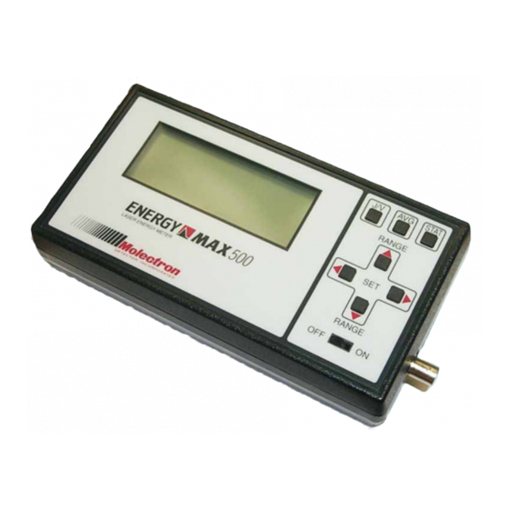
Thank you for purchasing a Molectron EM400/EM500. These devices are portable, battery-operated, single-channel laser joulemeters for production line testing and field service applications. Microprocessor-based instruments, they are designed to operate with Molectron's J25 and J50 series pyroelectric probes. The EM500 has an added computer interface capability. -
Page 10: Controls
Controls Arrow Keys Press the key to select a higher range in Normal or Average mode or to increase the value in Set functions. Press the key to select a lower range in Normal or Average mode or to decrease the value in Set functions. Press and/or to select digits in Set functions, to select a computation function (Average, Minimum,... -
Page 11: Indicators
Indicators Audible Tuning The Audible Tuning function can be entered from either Normal or Average mode. When enabled, the audible tone sets to 50% of its maximum frequency. When the initial reading (the reading at the moment the audible tone is enabled) is increased by 100%, the audible tone increases to 100%. -
Page 12: Battery Indicator
Battery Indicator The EM400 and the EM500 indicate when the battery is low. When lit, replace the 9V battery in the EM400 or recharge the internal battery in the EM500 with the supplied AC wall adapter. Note: Accurate readings cannot be made when the Battery Indicator is lit. DEV Indicator switches on when Standard Deviation is being displayed in Statistics mode. -
Page 13: Other Connectors
Other Connectors AC Wall Adapter Connector Located on the left side of the instrument, it connects to the wall adapter (supplied), allowing the unit to be powered from AC line power and the internal battery of the EM500 to be recharged. A replacement adapter, if needed, should be rated 18 V DC (±1 V DC), 500 mA. -
Page 14: Analog Out Connector
Example: The LCD reads 3.47 mJ on the 20 mJ range (about 17 percent of full scale). The analog output will read 0.347 VDC. Input BNC Connector Located on the right side of the instrument, the Input BNC connects to a Molectron J25 or J50 series pyroelectric probe. -
Page 15: Rs-232 Rj11 Connector
RS-232 RJ11 Connector To access the RS232 connector, press down on the compartment cover on the back of the EM500. Slide it outward, away from the center of the instrument. The RJ11 connector provides a 3-wire interface with an IBM compatible computer through a standard 25-pin or 9-pin D sub connector. -
Page 16: Safety & Maintenance
• Do not operate with suspected failures. If you suspect that this product is damaged, have it inspected by qualified Molectron service personnel. • Do not operate this product from a power source that applies more than the voltage specified. -
Page 17: User Maintenance
User Maintenance When the instrument activates , the EM400 battery must be replaced or the EM500 battery must be recharged. Energy readings are not accurate while the instrument displays Replace the EM400's battery by pressing down on the battery compartment cover located on the back of the instrument. Slide it outward, away from the center of the instrument. -
Page 18: Service & Calibration
To maintain optimum NIST traceable performance, return the instrument to Molectron for annual recalibration. In addition to recalibration, Molectron takes advantage of this annual service to upgrade firmware if necessary and verify the unit functions within Molectron's strict performance standards. -
Page 19: Operation
Operation A Typical Energy Measuring energy using and EM400/EM500 and a Molectron Pyroelectric Detector is easy. For a complete list Measurement of compatible Detectors, see Compatible Probes & Ranges. CAUTION: Do not exceed the power/energy density for the probe. Consult the detector data sheet, or test the setup with a damage test slide as appropriate. -
Page 20: Normal Mode
Normal Mode Normal mode displays the instantaneous energy of the laser on a pulse-to-pulse basis. Press to enter Normal mode. J/V Selection The EM400/EM500 can display Joules (J), millijoules (mJ), or microjoules (µJ); or Volts (V), millivolts (mV), or microvolts (µV). From Normal mode, press to shift between Joules and Volts. -
Page 21: Calibration Set Function
Calibration Set Function Before operating the EM400/EM500 with a probe, the correct calibration factor (Responsivity or Rv) for that probe must be entered. The probe Rv number is printed on the probe label in units of Volts/Joule. If the Rv number is printed in units of Volts/millijoule, multiply this number by 1000 to get Volts/Joule. -
Page 22: Avererage Mode
Average Mode Average mode provides pulse smoothing (reducing pulse-to-pulse variation). It calculates and displays a user-selected pulse average. Press to enter Average mode. The AVG annunciator will flash. Average Pulse Set Function Use this function to select a pulse average. 1. -
Page 23: Statistics Mode
Statistics Mode Statistics mode accumulates a set of pulses (2 to 9,999) and provides four kinds of numeric results (Average, Minimum, Maximum, and Standard Deviation) for the accumulated batch. The batches can be set to restart automatically at the end of each batch or only when is pressed. -
Page 24: Statistics Functions
Statistics Functions After the EM400/EM500 accumulates a batch of pulses, the results are displayed as one of four computations: Average, Minimum, Maximum, and Standard Deviation. 1. While in Statistics Mode, press until the annunciator for the desired function is steadily activated. -
Page 25: Remote Operation
Remote Operation Serial Port Parameters The EM500 accepts single-byte commands via the 3-wire RS-232 serial port. The EM500 sends a data stream of raw ADC readings representing joulemeter pulses. These readings must be scaled by the computer to display Joules or Volts. Only Normal mode functions are accessible from the RS-232 port. -
Page 26: Adc Data Format
ADC Data Format The ADC counts are transmitted in two-byte format. The two most significant bits (MSBs) of Data Byte 1 are always both set to 1 and bits seven and six are set to 1 and 0, respectively. Data Byte One Data Byte Two The six least significant bits (LSBs) of Data Byte One represent the six MSBs of the ADC counts. -
Page 27: Commands
Commands The EM500 operates serially one byte at a time. Upon receiving a valid command or auxiliary data byte, the EM500 returns an ACK (06 hex or dec). The single exception is data stream transmission, where the EM500 sends two bytes for every joulemeter pulse. -
Page 28: Query Full Scale Reading
Query Full Scale Reading 34 dec 22 hex " ASCII The EM500 transmits the ADC counts that produce 2000 counts on the EM500 display for the current range. The number, a 4-digit ASCII, is used to interpret the EM500 readings sent in raw ADC count format. Example: The EM500 is on the 2.000 Joule range. -
Page 29: Query Responsivity
Query Responsivity 35 dec 23 hex # ASCII Auxiliary Send Bytes: none Response Bytes: ASCII 3-digit mantissa with decimal, ASCII 'E', ASCII exponent sign '-' for negative exponents, ASCII 1-digit exponent (Rv in format X.XXEX or X.XXE-X). Restore Default Setup 62 dec 3E hex >... -
Page 30: Set Joules Measurement
Set Joules Measurement 48 dec 30 hex 0 ASCII Auxiliary Send Bytes: none Response Bytes: none Set Range 47 dec 2F hex / ASCII Set range from 2mJ to 20J or 2mV to 20V. Non-valid range requests are ignored. Auxiliary Send Bytes: ASCII 2-digit range exponent. Example: 0.002 range has exponent -3 (hex 2D 33). Response Bytes: none Set Responsivity 46 dec... -
Page 31: Start Data Transmission
Start Data Transmission 60 dec 3C hex < ASCII Auxiliary Send Bytes: none Response Bytes: Transmits two bytes for each joulemeter pulse received. Data is transmitted in raw ADC count format. NOTE: The EM500 display is not updated while RS232 data transmission is enabled. Also note that data bytes are transmitted only when the EM500 is receiving input pulses greater than the 5% trigger level. -
Page 32: Compatible Detectors & Ranges
Compatible Detectors & Ranges... -
Page 33: Frequently Asked Questions
From where can the source code Molectron does not supply the source code for this compiled application. Download EM500 LabVIEW tools from for the EM500 Application the Molectron website (www.molectron.com) for a better understanding of the communication protocols, or locate Program be downloaded? an RS-232 FAQ for more detailed information. - Page 34 How can I communicate with an 1. Doubleclick the Hypertrm.exe icon. EM500 using Microsoft's 2. For the Connection Description, use EM500. Hyperterminal? 3. At the Connect To window, select Direct to Com1 (or whichever port you're using). 4. At the COM Properties window, select the following parameters: •...
-
Page 35: Specifications
Specifications Instrument Specifications Display 4-digit numeric LCD Two alphanumeric characters Annunciators for trigger, statistics functions, and low battery Ranges Five Volt ranges: 2mV, 20mV, 200mV, and 20V Available Joule ranges depend on selected Responsivity Maximum Input Voltage: 9 VDC Maximum Input Pulse Amplitude 9 Volts peak Minimum Input Trigger Level 5% of full scale... - Page 36 Calibration Factors 1.00 x 10 to 9.99 x 10 EM500 Analog Output 2 volts full scale 100 Ω Output Impedance Data Conversion Digital 12-bit resolution Resolution EM500 RS-232 Interface 3-wire, polled operation EM500 RS-232 Baud Rate 9,600 (default) or 19,200 EM500 RS-232 Parity None EM500 RS-232 Data Bits...
- Page 37 EM500 Battery Recharge Time 14 hr Battery AUTO-OFF Timeout 5 min Dimensions 20.62 cm x 10.16 cm x 5.72 cm (8.12 in x 4.0 in x 2.25 in) plastic enclosure Weight, EM400 419.6 g (14.8 oz) Weight, EM500 632.2 g (1 lb, 6.3 oz) Factory Default Settings Before shipment, the attributes of the EM400/EM500 are set as follows: Measurement Mode:...
- Page 38 Warranted Characteristics Power 90-264 VAC, 47-63 Hz, 25 VA Atmospherics Temperature Operating, 0° C to +50° C Storage, -40° C to +75° C Maximum operating temperature is decreased 1° C per 305 m (1,000 ft) above 1,525 m (5,000 ft) Relative Humidity 0-95% at or below +30°...
- Page 39 Susceptibility Meets or exceeds the requirements of the following standards EN 50082-1 European Community Requirements IEC 802-2 Electrostatic Discharge, Performance Criteria B IEC 801-3 Radiated Susceptibility 3 V/meter from 27MHz to 500MHz unmodulated Performance Criteria: Maximum meter deviation ±3% of reading Maximum LCD reading ±3% of reading IEC 801-4 Electrical Fast Transient/Burst...
Need help?
Do you have a question about the ENERGY MAX EM400 and is the answer not in the manual?
Questions and answers