
Related Manuals for Molectron EPM1000


Summary of Contents for Molectron EPM1000
- Page 1 (217) 352-9330 | Click HERE Find the Coherent / Molectron EPM1000 at our website:...
- Page 2 USER’S GUIDE EPM1000 JOULEMETER/POWER METER USER’S GUIDE Artisan Technology Group - Quality Instrumentation ... Guaranteed | (888) 88-SOURCE | www.artisantg.com...
- Page 3 Artisan Technology Group - Quality Instrumentation ... Guaranteed | (888) 88-SOURCE | www.artisantg.com...
- Page 4 EPM1000 SINGLE CHANNEL JOULEMETER/POWER METER USER’S GUIDE Artisan Technology Group - Quality Instrumentation ... Guaranteed | (888) 88-SOURCE | www.artisantg.com...
- Page 5 (800) 366-4340 (503) 620-9069 FAX: (503) 620-8964 http://www.molectron.com Copyright 1998 by Molectron Detector, Inc. © All rights reserved. No portion of this book may be reproduced or transmitted in whole or in part in any form or by any means without permission of the publisher.
-
Page 6: Table Of Contents
Overview Unpacking and Inspecting the Instrument Safety Information Manual Information Features Interface Units and Ranges Compatible Probes Understanding the EPM1000 Internal Trigger Understanding the EPM1000 External Trigger Understanding the EPM1000 Speedup Feature Description Rear Panel Front Panel Operation Tutorial Thermopile... - Page 7 Instrument Calibration and Service Specifications Electrical/Mechanical Display Ranges Resolution Maximum Rep Rate Linearity A/D Digital Resolution Input Impendance Noise Equivalent Voltage (NEV) Analog Output External Trigger Input EPM1000 User’s Guide Artisan Technology Group - Quality Instrumentation ... Guaranteed | (888) 88-SOURCE | www.artisantg.com...
- Page 8 Power Requirements Dimensions Weight Firmware Revisions Factory Defaults Warranted Characteristics Power Atmospherics (Temperature) Atmospherics (Relative Humidity) Atmospherics (Altitude) Dynamics (Random Vibration) Emissions Susceptibility Index EPM1000 User’s Guide Artisan Technology Group - Quality Instrumentation ... Guaranteed | (888) 88-SOURCE | www.artisantg.com...
- Page 9 Table of Contents EPM1000 User’s Guide Artisan Technology Group - Quality Instrumentation ... Guaranteed | (888) 88-SOURCE | www.artisantg.com...
-
Page 10: Features & Description
Features & Description Welcome Overview Thank you for purchasing an EPM1000. The EPM1000 is a laboratory, AC powered meter that can measure both pulsed and CW lasers: energy, power, voltage, and (pulsed only) frequency. The EPM1000 is compatible with all of Molectron Detector, Inc.’s pyroelectric, silicon, and PowerMax... -
Page 11: Safety Information
Review this safety information carefully to avoid injury and prevent damage to this instrument or any instrument connected to it. There are no user serviceable parts in the EPM1000. For Service, please see Maintenance, Service, and Calibration. This manual uses two terms to describe hazardous conditions: Caution and Warning. -
Page 12: Manual Information
PageMaker Features Interface The EPM1000 features a standard RS-232 9-pin connector on the back panel. This can connect to any similar RS-232 port of a host PC. IEEE-488 (or GPIB) interface is standard on every EPM1000. Use this port for the following advantages: •... -
Page 13: Compatible Probes
Set the trigger level for at least 2% above the noise level and at least 2% below the peak height. For example, with a peak height of 300 mJ, set the EPM1000 to a range of 3 J. A peak will occur at 10% of full scale, well above the 5% level. - Page 14 From the trigger point forward, the algorithm searches for peaks and from the trigger point back, it searches for a baseline. The EPM1000 can be programmed to ignore triggers for a specified time after a valid trigger. This prevents “false” triggers in pulse tails from accidentally starting a new sample (see Figure 2).
-
Page 15: Understanding The Epm1000 External Trigger
Features & Description The external trigger for the EPM1000 is a 100Ω resistor (R64) in series Understanding the with an optical coupler (U39). The coupler is protected by an additional EPM1000 External diode (CR20). A high signal at the BNC forward biases the optocoupler Trigger Circuit diode and triggers the EPM1000. -
Page 16: Understanding The Epm1000 Speedup Feature
Speedup feature. The fastest and most accurate results can be achieved when the Speedup feature is in Selective mode. In Selective mode, the EPM1000 deter- mines when the Speedup algorithm should be used. Whenever the actual... -
Page 17: Description
For example, if the EPM1000 is set on the 300 mJ range, then the Analog Out value will be 1.81 V when the input pulse is 300 mJ. If the input pulse were 150 mJ, then the Analog Out value would be approximately 905 mV. - Page 18 This input line accepts synchronized pulses from the laser. It is electri- (continued) cally isolated from the EPM1000 and consists of a 100Ω resistor in series with an optoisolator. It can be set from the front panel or via remote to trigger on the rising or falling edge of the input signal. This input only triggers pyroelectric/silicon measurements.
-
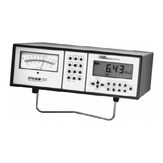
Page 19: Front Panel
Analog Meter Zero Adjustment Screw Figure 7: EPM1000 Front Panel Digital Display Twelve different readouts appear on the EPM1000's liquid crystal display (see Figure 6). • REM Annunciator Indicates the EPM1000 is under remote control. • Numeric Display Typically indicates measurement value. - Page 20 (0-10 or 0-3) is being used. • Sign Indicator Indicates a negative reading during thermopile measurements. • TRG Annunciator Indicates the EPM1000 is receiving a valid input pyroelectric/silicon pulse. EPM1000 User’s Guide Artisan Technology Group - Quality Instrumentation ... Guaranteed | (888) 88-SOURCE | www.artisantg.com...
- Page 21 Features & Description Front Panel Function Keys Nine different keys control the primary functions of the EPM1000. (Continued) Sets the instrument to report incoming energy in Joules during pyroelectric/silicon measurements. Sets the instrument to report probe output in Volts -- pulse height for pyroelectric/silicon measurements, DC voltage during thermopile measurement.
- Page 22 Analog Meter The EPM1000's analog meter uses two scales, one marked 0-10 and one marked 0-3. The 1 and 3 scale indicators on the LCD indicate respec- tively which scale the EPM1000 is using.
- Page 23 Features & Description EPM1000 User’s Guide Artisan Technology Group - Quality Instrumentation ... Guaranteed | (888) 88-SOURCE | www.artisantg.com...
-
Page 24: Operation
PowerMax ® thermopile probe. ! Caution Connecting or disconnecting a probe while the EPM1000 is on will damage the probe. 2. Connect the detector to the EPM1000 rear panel 25- pin Smart Probe connector, using the probe's cable. -
Page 25: Pyroelectric
® probe, it monitors the pyroelectric/silicon input for signal peaks. The EPM1000 will not automatically read the probe's responsivity as it does with a thermopile probe, so the responsivity must be programmed separately. Warning: Follow all laser safety procedures. Laser must be blocked or ! Warning switched off before beginning this procedure. -
Page 26: Modes
AUTO While in Normal Mode, measuring Joules, Volts, or Watts, press set the EPM1000 in Auto Mode. The next pulse is used to determine the proper range and while the EPM1000 is seeking this range, the annunciator blinks. The annunciator stops blinking and locks on when the EPM1000 has located the proper range. -
Page 27: Statistics Mode
Use Statistics Mode to measure statistical qualities of a predetermined number of samples. This number, the Statistics Batch Size, can be 0 or any number from 2 to 9999. The EPM1000 can be programmed to stop after taking a single batch (Manual Restart Mode), or continue sampling a new statistical batch (Automatic Restart Mode). - Page 28 Operation System Settings Average Batch Size The number of samples in the EPM1000's Average Batch Size can be (Continued) any value from 2 to 99. To change the quantity, press . The LCD will indicate the current value. For example, a value of 57 samples looks like Change the value directly with the numeric Entry Keys.
- Page 29 To change the pyroelectric responsivity, press . The current pyroelectric responsivity will be displayed. For example, if the current responsivity is 2200 V/J, then the EPM1000 LCD will read Use the keys to change the exponent and exponent sign. Use the Numeric Entry Keys to change the decimal value. When complete, press to complete the action.
- Page 30 Operation System Settings Statistics Batch Restart Mode The EPM1000 handles the end of a statistical batch in one of two (Continued) different ways. In Automatic Restart Mode, at the then of a batch, the EPM1000 automatically begins collecting the next batch. The calculated statistical values are displayed on screen until the new batch has been collected.
-
Page 31: Trigger Settings
EPM1000 will not permit an invalid value. Press to complete the action. Trigger Level The EPM1000 internal trigger level can be set for as low as 2% of full scale and as high as 20% of full scale. Noisy environments require higher trigger levels. TRIG To set the EPM1000's trigger level, press . -
Page 32: Communications Settings
Communications Settings IEEE-488 Address Set the EPM1000 IEEE-488 address to any value from 1 to 31. Although the EPM1000 can use address 0, this is not recommended, as the IEEE-488 bus expects the instrument at address 0 to be a Controller. - Page 33 RS-232 Stop Bits The RS-232 data stream from the EPM1000 can be set to contain one or two stop bits. Set the number of stop bits by pressing and then until the LCD reads .
-
Page 34: Programming
Commands can be separated by a space, a colon (:), or a tab. Commands preceded by a semicolon (;), an asterisk (!), or a pound sign (#) are read as comments by the EPM1000 and ignored. -
Page 35: Audible Beeper
Response syst opt aud off none syst opt aud ? SYSTEM: OPTION: AUDIO OFF Average Batch Size Set or query the Average Mode Batch Size of the EPM1000. Command Form CHannel AVERage BATch_size <?|2..99> Examples Input Response ch aver bat 42... -
Page 36: Communications Error
Response comm error on none syst opt bak off Unrecognized SCPI command: syst opt bak off Display Current Reading Query the EPM1000 for the data currently displayed on the LCD. Command Form CHannel QUERY Examples Input Response ch query CHAN: QUERY: 227.4 mV... -
Page 37: Line Frequency
OUTPUT: BUFFER FIXED Output Continuous Set the EPM1000 to either continuously transmit data or store data in its internal buffer. To continuously transmit data via RS-232, the DTR line must remain asserted. If storing data, the EPM1000 will transmit all of its data upon receiving an command. -
Page 38: Output Depth
Programming Output Depth Set or query the depth of the EPM1000 buffer in bytes, any value from 1 to 4095. Command Form OUTput DEPth <?|1..4095> Examples Input Response out dep 1000 none out dep ? OUTPUT: DEPTH 1000 Output Dump Query the EPM1000 buffer contents, but only when is off. - Page 39 Status Bytes decode as follows: Bit 7 Always 0 Bit 6 Channel 0 = Channel A 1 = Channel B (not used on EPM1000) Bit 5 Information Type 0 = Range Information 1 = Unit Information Bits 4-0 (If Range Information) Range...
- Page 40 Figure 10: Data High Byte Map Meaning d5 d4 d3 d2 d1 d0 Figure 11: Data Low Byte Map For example, an EPM1000 dumps its buffer. The following data is transmitted: . Translated: 38 21 00 A6 C3 A6 CA 3C 38 = 0011 1000 Status Byte, CH A, Unit Information, "Command Completed"...
-
Page 41: Probe Type
? OUTPUT: FORMAT BINARY Probe Type Query the EPM1000 to determine the type of probe attached. In the ® case of a PowerMax probe, the EPM1000 will also return the head code in hexadecimal notation. -
Page 42: Range, Maximum/Minimum
*RST Example Input Response *rst < unit resets > Responsivity Set or query the pyroelectric or thermopile responsivity of the EPM1000. Express the value in decimal or scientific notation. Command Form CHan RESPonsivity <THERmopile|PYROelectric> <?| value > Examples Input Response... -
Page 43: Rs-232 Parity
Response comm rs232 par even none comm rs232 par ? COMM: RS232: PARITY EVEN RS-232 Stop Bits Set or query the number of stop bits the EPM1000 injects into the communications stream. Command Form COMMunication RS232 STOPbits <?|1|2> Examples Input... -
Page 44: Statistics Batch Size
? CHAN A: STAT: BATCH_SIZE 6126 Statistics Restart Mode Set or query the EPM1000's action at the end of a statistical batch. Manual requires a restart signal, such as , automatic will ch stat start begin a new batch immediately upon logging the data from the previous batch. -
Page 45: Statistics Start
CHan STATistics START Examples Input Response ch stat start <batch restarts> Trigger Level Set or query the trigger level of the EPM1000. Values accepted are 2 through 20. Command Form CHan TRIGgering LEVel <?|2..20> Examples Input Response ch trig lev 18... -
Page 46: Zero
Programming Zero In thermopile mode, this command sets the current probe input voltage as a zero baseline value. While taking a statistics measurement, the EPM1000 will reset the batch upon receiving this command. Command Form CHan ZERO Examples Input Response <... -
Page 47: Programming Example
Programming The following example shows the necessary commands to set the Programming EPM1000 to collect a statistical batch of 100 samples from a 1kHz laser. Example The probe responsivity is 220 V/J. The binary data are stored in the EPM1000's buffer until download via the out dump command. The buffer depth has been set to the maximum value to allow the greatest time between data dumps. -
Page 48: Maintenance, Service, & Calibration
Verify the COM port works with other devices. Add a CR (Carriage Return, ASCII 13) to the end of a command string. The EPM1000 may be in the middle of collecting the first of a series of command ch units ? statistical batches. - Page 49 300 ms is ideal, although some commands are not always commands will execute in less time. implemented. If the EPM1000 is set for continuous output, the buffer will not contain The EPM1000 won't save data and the command will be ignored. Deactivate the...
-
Page 50: Fuse Replacement
Figure 13: Removing the EPM1000 fuse, and the spare fuse compartment. Caution: If the EPM1000 blows two or more fuses in a short period of ! Caution time, turn the unit off, disconnect it from the AC supply, and contact Molectron Detector, Inc. - Page 51 5. Seal the shipping carton with shipping tape or an industrial stapler. Calibration and Service 6. On the outside of the package, clearly print the RMA number. (continued) EPM1000 User’s Guide Artisan Technology Group - Quality Instrumentation ... Guaranteed | (888) 88-SOURCE | www.artisantg.com...
-
Page 52: Specifications
• Update Rate 3 Hz External Trigger Input • Optically coupled • 100 Ω in series with LED • Rising/falling edge trigger via user control. EPM1000 User’s Guide Artisan Technology Group - Quality Instrumentation ... Guaranteed | (888) 88-SOURCE | www.artisantg.com... -
Page 53: Electronic Accuracy
Weight • 1.41 kg (3.1 lbs) Firmware Revisions Every EPM1000 contains two programmed chips, one for the analog board and one for the digital board. Knowing the firmware revisions of these chips is useful when calling Molectron Detector, Inc. Press to determine the digital firmware revision. -
Page 54: Factory Defaults
0.31 g rms, from 5 to 500 Hz, 10 minutes each axis. Dynamics ( Random Vibration Non-operating 2.46 g rms, from 5 to 500 Hz, 10 minutes each axis. EPM1000 User’s Guide Artisan Technology Group - Quality Instrumentation ... Guaranteed | (888) 88-SOURCE | www.artisantg.com... -
Page 55: Emissions
500 MHz unmodulated. Performance Criteria: Maximum meter deviation ±3% of reading. Maximum LCD reading deviation ±3% of reading. • IEC 801-4 Electrical Fast Transient/Burst EPM1000 User’s Guide Artisan Technology Group - Quality Instrumentation ... Guaranteed | (888) 88-SOURCE | www.artisantg.com... -
Page 56: Index
Average Batch Size Average Mode, see Modes, Average ch mem recall, see Channel Recall Average Mode, Setting the EPM1000 for, 12, 18 ch mem store, see Channel Store AVG Annunciator, see Annunciator, AVG ch oper stat, see Operating Mode... - Page 57 DCE (Data Communications Equipment), 9 IEC 801-4, see Warranted Characteristics, Susceptibility Defaults, Factory, 19, 45 IEC 802-2, see Warranted Characteristics, Susceptibility Reprogramming the EPM1000 with, 19 IEEE-488 Delay Time for Commands, 40 Address, 23, 27 DEV Annunciator, see Annunciator, DEV...
- Page 58 ® Linearity, see Specifications Function, 39 loc, 25 Thermopile Probes, 1, 8, 39 Local Control, Returning the EPM1000 to, 25 Probe Data, Incoming, 17 Manual Information, 3 Probe Type, 32 Manual Restart Mode, see Statistics Batch Restart Mode, Manual Probe, Properly Aligning, 39...
- Page 59 Speedup Service, 2, 41 System Keys, see Keys, System SET Key, see Keys, SET Temperature, Operating, see Warranted Characteristics, Atmospherics Shipping an EPM1000, 41 Thermopile Shipping Carton, 41 Output Noisy, 39 Sign Indicator, 11 Probes, 1, 4...
- Page 60 Valid/Invalid Pulses (Figure), 4 Variations, Pulse-to-Pulse, Reducing, 17 Ventilation, 2 Vibration, see Warranted Characteristics, Dynamics Virtual Instrument, 38 Volts Key, see Keys, Volts Volts, Setting the EPM1000 for, 12 Warning Condition, Definition, 2 Warranted Characteristics Atmospherics, 45 Dynamics, 45 Emissions, 46...
- Page 61 Index EPM1000 User’s Guide Artisan Technology Group - Quality Instrumentation ... Guaranteed | (888) 88-SOURCE | www.artisantg.com...
Need help?
Do you have a question about the EPM1000 and is the answer not in the manual?
Questions and answers