
Related Manuals for Winradio WR-ETC-100


Summary of Contents for Winradio WR-ETC-100
- Page 1 WiNRADiO ® WR-ETC-100 (for the G35DDCi) Multichannel Coherent Application Guide for the Extended Topology Configuration option (ETC) Version 1.0...
-
Page 2: Table Of Contents
Introduction ........................... 4 2. Parts description of the coherent system ................6 2.1 WR-G35DDCi connectors .................... 6 2.2 The WiNRADiO Coherence Clock & 1PPS Kit (WR-CC1PPS-100) ......7 2.2.1 Coherent clock generator board ................8 2.2.2 PCIe connector ...................... 9 2.2.3 SMA connectors for sampling clock output ............ - Page 3 2.3.8 30 cm SMA sampling clock patch cable ..............19 2.3.9 SMA coaxial cables for the sampling clock and synchronization ......20 2.4 The WiNRADiO PCIe Bracket Multi-SMA Adapter ............22 3. ETC installation of up to eight receivers ................23 3.1 Preparing the receivers for installation into a PC ............26 3.2 Installing the receiver into a PC ...................28...
-
Page 4: Introduction
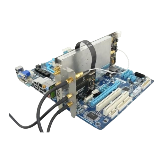
WiNRADiO. Moreover, in Extended Topology Configuration (ETC), each WR-G35DDCi receiver has to be equipped with the WR-ETC-100 ‘WiNRADiO Extended topology Configuration kit’ (ETC kit). Therefore, for ETC configuration, the number of ETC kits needed is equal to number of WR-G35DDCi receivers in the coherent multichannel group. - Page 5 WR-G35DDCi Multichannel Coherent Application Guide for Extended topology configuration (ETC) An example of a one receiver, forming part of a multichannel coherent system in ETC configuration is shown in Picture 1-2. Picture 1-2: An example of a one WR-G35DDCi receiver, forming part of a multichannel coherent system in ETC configuration with the ETC kit, installed into a PC (PC chassis and other PC connections omitted for clarity).
-
Page 6: Parts Description Of The Coherent System
WR-G35DDCi Multichannel Coherent Application Guide for Extended topology configuration (ETC) Parts description of the coherent system 2.1 WR-G35DDCi connectors The connectors required for coherent operation of the WR-G35DDCi receivers are shown in Pictures 2-1 and 2-2 (present when the /CR option has been fitted): Picture 2-1: Rear panel connectors of the WR-G35DDCi Picture 2-2: Digital synchronization connector of the WR-G35DDCi, viewed on the PCB side... -
Page 7: The Winradio Coherence Clock & 1Pps Kit (Wr-Cc1Pps-100)
WR-G35DDCi Multichannel Coherent Application Guide for Extended topology configuration (ETC) 2.2 The WiNRADiO Coherence Clock & 1PPS Kit (WR-CC1PPS-100) The ‘WiNRADiO Coherence Clock & 1PPS Kit’ (hereafter referred to as the 'Clock Kit') provides production and distribution of a coherent 100 MHz clock for up to eight WR-G35DDCi receivers as well as digital synchronization of the receivers. -
Page 8: Coherent Clock Generator Board
WR-G35DDCi Multichannel Coherent Application Guide for Extended topology configuration (ETC) 2.2.1 Coherent clock generator board The Coherent clock generator board is shown in Picture 2-4. It is a PCIe card, which has to be installed into PCIe slot inside a PC. The board generates a 100 MHz sampling clock for up to eight WR-G35DDCi receivers. -
Page 9: Pcie Connector
WR-G35DDCi Multichannel Coherent Application Guide for Extended topology configuration (ETC) 2.2.2 PCIe connector The PCIe connector provides power to the Coherent clock generator board. As there is no data communication running through the PCIe connector, no software driver is required for proper operation of the board. -
Page 10: Frequency Reference Output Ref Out
WR-G35DDCi Multichannel Coherent Application Guide for Extended topology configuration (ETC) 2.2.5 Frequency reference output REF OUT The frequency reference output is an SMA connector providing the 10 MHz (internally derived) frequency reference output signal. This output can be connected to the REF IN input port (Section 2.2.6) if the internal frequency reference operation of the board is required. -
Page 11: Sma Patch Cables For Coherent Clock Distribution
Section 2.4. The cable carries the clock signal out of the PC chassis to distribute it to all WR-G35DDCi receivers which are in coherent operation. For interconnection, only use the original WiNRADiO SMA patch cables supplied with the Clock Kit as these are specially matched to be coherent. -
Page 12: Digital Synchronization Cable For The Coherent Clock Generator Board
WR-G35DDCi Multichannel Coherent Application Guide for Extended topology configuration (ETC) 2.2.11 Digital synchronization cable for the Coherent clock generator board Similar to the digital synchronization cables described in the previous Section, this cable is unused in the ETC configuration, therefore do not install this cable. However, this cable should be kept safely, in case the Clock Kit is required to operate in standard (non-ETC) coherent receiver operation in the future. -
Page 13: Sma Terminators
WR-G35DDCi Multichannel Coherent Application Guide for Extended topology configuration (ETC) 2.2.13 SMA terminators The Clock Kit comes with eight 50 ohm SMA terminators. These terminators must occupy all unused sampling clock outputs on the Coherent clock generator board. If all sampling clock outputs on the Coherent clock generator board are connected to the ‘PCIe bracket multi-SMA adapter’... -
Page 14: Sampling Clock Oscillator Input And Outputs
WR-G35DDCi Multichannel Coherent Application Guide for Extended topology configuration (ETC) 2.2.14 Sampling clock oscillator input and outputs The Coherent clock generator board has two sampling clock oscillator outputs and one input for the sampling clock oscillator. These are factory connected as shown in Picture 2-12 using an SMA jumper cable as described in Section 2.2.15, and one SMA 50 ohm terminator. -
Page 15: Pin Header For Disabling The Sampling Clock Oscillator
WR-G35DDCi Multichannel Coherent Application Guide for Extended topology configuration (ETC) 2.2.16 Pin header for disabling the sampling clock oscillator The 'pin header' for disabling the sampling oscillator is shown in picture 2-13 with its corresponding jumper is shown in picture 2-14. No jumper is installed on the header for normal operation of a single Coherent clock generator board. -
Page 16: The Winradio Etc Kit (Wr-Etc-100)
WR-G35DDCi Multichannel Coherent Application Guide for Extended topology configuration (ETC) 2.3 The WiNRADiO ETC kit (WR-ETC-100) The ‘WiNRADiO ETC kit’ (hereafter referred to as the 'ETC Kit') provides coherent synchronization capability between multiple WR-G35DDCi receivers operating in ETC mode. A single ETC kit is needed for each WR-G35DDCi receiver. In other words, the number of required ETC kits is equal to the number of coherent receivers. -
Page 17: Etc Kit Board
WR-G35DDCi Multichannel Coherent Application Guide for Extended topology configuration (ETC) 2.3.1 ETC kit board The ETC board is shown in Picture 2-16. This is a PCIe card, which has to be installed into a PC, next to and connected to each WR-G35DDCi receiver; one ETC board is required for each receiver. -
Page 18: Pcie Connector
The SYNC IN connector on the first-in-chain board can be left unconnected. Alternatively, it can be used as the input for the 1PPS signal, when timestamping functionality is required. The synchronization protocol utilized on this interface is proprietary to WiNRADiO, therefore no further specification is provided. -
Page 19: Sma Adapter For The Sampling Clock
WR-G35DDCi Multichannel Coherent Application Guide for Extended topology configuration (ETC) 2.3.6 SMA adapter for the sampling clock The SMA adapter for the sampling clock allows for entrance of the sampling clock to the PC chassis interior. In ETC configuration, all connections between receivers and the Coherent clock generator board (see Section 2.2.1) are done externally to the chassis of the PCs. -
Page 20: Sma Coaxial Cables For The Sampling Clock And Synchronization
WR-G35DDCi Multichannel Coherent Application Guide for Extended topology configuration (ETC) For interconnection, only use the original WiNRADiO 30 cm SMA sampling clock patch cable supplied with the ETC Kit, as it is specially matched to be coherent. Picture 2-18: The 30 cm SMA sampling clock patch cable 2.3.9 SMA coaxial cables for external connection of the sampling... - Page 21 SYNC CABLE in the last row, see the Picture 2-20 on the right. For interconnection, only use the original WiNRADiO SMA patch cables supplied with the ETC Kit as these are specially matched to be coherent. Do not mix different cable lengths or different cable types.
-
Page 22: The Winradio Pcie Bracket Multi-Sma Adapter
WR-G35DDCi Multichannel Coherent Application Guide for Extended topology configuration (ETC) The WiNRADiO PCIe Bracket Multi-SMA Adapter The WiNRADiO ‘PCIe Bracket Multi-SMA Adapter’ consists of eight SMA to SMA connector adapters mounted on a standard PCI bracket. It is designed to be installed into a standard PCIe card position slot inside a PC chassis. -
Page 23: Etc Installation Of Up To Eight Receivers
WR-G35DDCi Multichannel Coherent Application Guide for Extended topology configuration (ETC) 3. ETC installation of up to eight receivers The basic setup of up to eight receivers in the ETC configuration is shown in Picture 3-1, although only four receivers are shown in the picture for the picture clarity. A simplified version of an eight channel setup is shown in the Picture 3-2. - Page 24 WR-G35DDCi Multichannel Coherent Application Guide for Extended topology configuration (ETC) Picture 3-1: Sampling clock and digital sync signal interconnection of four WR-G35DDCi/CR receivers in ETC configuration.
- Page 25 WR-G35DDCi Multichannel Coherent Application Guide for Extended topology configuration (ETC) Picture 3-2: Sampling clock and synchronization interconnection of eight WR-G35DDCi/CR receivers in ETC configuration. Channels 3 to 7 are identical to channels 1,2 and 8.
-
Page 26: Preparing The Receivers For Installation Into A Pc
WR-G35DDCi Multichannel Coherent Application Guide for Extended topology configuration (ETC) 3.1 Preparing the receivers for installation into a PC Prior to installation into a PC, attach the 30 cm SMA sampling clock patch cable of the ETC kit (described in Section 2.3.8) to the Coherent clock input of each receiver, leaving the other end of cable unconnected for now. - Page 27 WR-G35DDCi Multichannel Coherent Application Guide for Extended topology configuration (ETC) Picture 3-4: Installing the FPC connector (for clarity, the cable shown here is of another color) Picture 3-5: Digital synchronization cable installed to a receiver. The cable orientation is arbitrary, either end of the cable can be installed to the connector of the receiver.
-
Page 28: Installing The Receiver Into A Pc
WR-G35DDCi Multichannel Coherent Application Guide for Extended topology configuration (ETC) 3.2 Installing the receiver into a PC A PC has to be powered off when installing the receiver into a PCIe slot. Each receiver has to be prepared for installation as discussed in Section 3.1. As mentioned earlier, in the ETC configuration, each WR-G35DDCi receiver is typically installed in a separate dedicated PC. -
Page 29: Installing The Etc Board Into The Pc
WR-G35DDCi Multichannel Coherent Application Guide for Extended topology configuration (ETC) 3.3 Installing the ETC board into the PC As mentioned in the previous step, the PC has to be powered off when installing the ETC board into a PCIe slot. Prior to inserting the ETC card into a PCIe slot, interconnect the ETC card to the receiver which is already installed in PC, as described in previous Section. - Page 30 WR-G35DDCi Multichannel Coherent Application Guide for Extended topology configuration (ETC) Picture 3-8: The completed installation of the ETC board into the PC next to the receiver. Picture 3-9: The completed installation of the receiver (shown on the left) and the ETC board (shown on the right) fitted into the PC as seen from the rear of the PC.
-
Page 31: Interconnecting The Coherent Clock Generator Board
WR-G35DDCi Multichannel Coherent Application Guide for Extended topology configuration (ETC) Interconnecting the Coherent Clock Generator board with the PCIe bracket multi-SMA adapter Prior to installation of the Coherent clock generator board (described in Section 2.2.1) into the PC, interconnect the Coherent Clock Generator board with the PCIe bracket multi-SMA adapter (described in Section 2.4) using eight SMA patch cables supplied with the Clock Kit described in Section 2.2.9. -
Page 32: Installing The Coherent Clock Generator Board Into The Pc
WR-G35DDCi Multichannel Coherent Application Guide for Extended topology configuration (ETC) Picture 3-10: This is an example of interconnection of the Coherent Clock Generator board of the Clock Kit with the PCIe bracket multi-SMA adapter. Interconnection is made using 45 cm SMA patch cables of the Clock kit. This interconnection is also shown schematically as a part of Picture 3-1 and Picture 3-2. - Page 33 WR-G35DDCi Multichannel Coherent Application Guide for Extended topology configuration (ETC) There is no requirement for the Clock Board to be installed in a specific PC. It can be installed in a PC together with any receiver it feeds, but doesn’t have to be installed together with any receiver at all.
- Page 34 WR-G35DDCi Multichannel Coherent Application Guide for Extended topology configuration (ETC) Picture 3-12: The completed installation of the Coherent Clock Generator board (on the left) into the PC together with the PCIe bracket multi-SMA adapter (on the right) installed next to the Clock Board as viewed from the rear side of a PC.
-
Page 35: Choosing The Frequency Reference
WR-G35DDCi Multichannel Coherent Application Guide for Extended topology configuration (ETC) Choosing the frequency reference When using the internal frequency reference, please connect the internal reference output REF OUT of the Coherent clock generator board to the frequency reference input REF IN of the Coherent clock generator board, after it has been installed into a PC (as shown in Picture 3-13). -
Page 36: Connecting The Clock Interconnection
Cables of various types and lengths cannot be used within one coherent group of receivers. For interconnection, only use the original WiNRADiO SMA CLOCK cables supplied with the Clock Kit as these are specially matched to be coherent. -
Page 37: Connecting The Sync Interconnection
WR-G35DDCi Multichannel Coherent Application Guide for Extended topology configuration (ETC) Picture 3-14: Connecting the sampling clock interconnection. The CLOCK cables described in Section 2.3.4 and 2.3.9 must be used for the interconnection. Picture 3-15: When connecting the sampling clock interconnection to less than eight receivers, SMA 50 ohm terminators must be installed on any unused clock output ports. - Page 38 The number of the receivers which can be synchronized is unlimited in theory, but currently it is limited to 16 by the software. If more than sixteen channels are required, please contact WiNRADiO. As mentioned above, the SYNC CABLES (described in Section 2.3.4 and 2.3.9). must be used for the SYNC interconnection.
-
Page 39: Connecting The 1Pps Signal
WR-G35DDCi Multichannel Coherent Application Guide for Extended topology configuration (ETC) Connecting the 1PPS signal The 1PPS signal can be connected to the SYNC IN SMA input of the ETC card designated as the master (connected to master receiver), as shown in Picture 3-17. Please note that, the 1PPS signal is not needed for coherent operation of the WR-G35DDCi receivers. -
Page 40: Extended Installation Of Up To Sixteen Receivers
To install more than eight and up to sixteen receivers as a single coherent group, two WiNRADiO Coherence Clock & 1PPS Kits (as described in chapter 2.2, the Clock Kits) as well as two PCIe Bracket Multi-SMA Adapters (as described in chapter 2.4) are needed. Two Coherent clock generator boards are interconnected and act as single Coherent clock generator board, providing 16 outputs of the coherent sampling clock. - Page 41 WR-G35DDCi Multichannel Coherent Application Guide for Extended topology configuration (ETC) Both Coherent Clock Generator Boards have to be interconnected, each with its respective PCIe bracket multi-SMA adapter as described in Section 3.4. Such a connection of sixteen channels is also shown schematically as a part of connection diagram in the Picture 4-3. This way sixteen coherent SMA clock outputs are provided at the rear of the PC where the Clock Boards are installed.
-
Page 42: Installation Of Receivers
WR-G35DDCi Multichannel Coherent Application Guide for Extended topology configuration (ETC) Picture 4-2: The jumper for disabling the sampling clock oscillator is installed on the slave board (marked in red). A blue jumper is used for picture clarity. Installation of receivers For installation of up to sixteen receivers please refer to Picture 4-3 and Chapter 3 of this document. - Page 43 WR-G35DDCi Multichannel Coherent Application Guide for Extended topology configuration (ETC) Picture 4-3: Sampling clock and digital sync signal interconnection of sixteen WR-G35DDCi receivers. Clock interconnect (marked in red) is described in Section 4.1.
-
Page 44: Technical Specification
WR-G35DDCi Multichannel Coherent Application Guide for Extended topology configuration (ETC) 5. Technical specification Output sampling frequency 100 MHz Sampling clock output level +2 dBm min. into 50 ohm Number of sampling clock output ports Reference frequency 10 MHz REF IN input impedance 50 ohm REF IN input level +2 dBm min. -
Page 45: Contacts
All rights reserved. No part of this book may be reproduced or transmitted in any form or by any means without the written permission of the publisher. Trademarks WiNRADiO, G3, G35DDC and Excalibur Ultra are trademarks of WiNRADiO Communications All other brand and product names are trademarks of their respective owners. Published in Australia... - Page 46 WiNRADiO ® C O M M U N I C A T I O N S w w w . w i n r a d i o . c o m...
Need help?
Do you have a question about the WR-ETC-100 and is the answer not in the manual?
Questions and answers