
Subscribe to Our Youtube Channel
Related Manuals for Winradio WR-G35DDCi


Summary of Contents for Winradio WR-G35DDCi
- Page 1 WR-G35DDCi Multichannel Coherent Application Guide WiNRADiO ® WR-G35DDCi Multichannel Coherent Application Guide...
-
Page 2: Table Of Contents
Table of contents Introduction ........................3 Parts description of the coherent system ..................4 WR-G35DDCi connectors ......................4 The WiNRADiO Coherence Clock & 1PPS Kit (WR-CC1PPS-100) ..........5 2.2.1 Coherent clock generator board with 1PPS input ............6 2.2.2 PCIe connector ........................ 7 2.2.3... -
Page 3: Introduction
Kits have to be used. For more than sixteen channels please contact WiNRADiO. For coherent operation, all WR-G35DDCi receivers must be clocked at exactly the same frequency and phase. To achieve this requirement, it is necessary to distribute a sampling clock from a single low phase noise clock source. -
Page 4: Parts Description Of The Coherent System
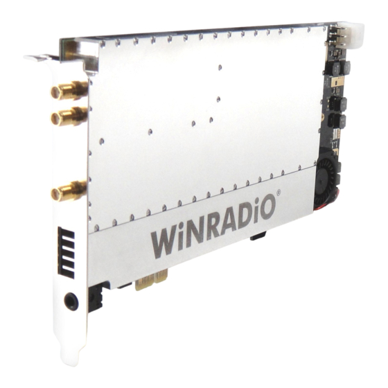
2 Parts description of the coherent system 2.1 WR-G35DDCi connectors The connectors required for coherent operation of the WR-G35DDCi receivers are shown in Pictures 2-1 and 2-2 (present when the /CR option has been fitted): Picture 2-1: Rear panel connectors of the WR-G35DDCi... -
Page 5: The Winradio Coherence Clock & 1Pps Kit (Wr-Cc1Pps-100)
The ‘WiNRADiO Coherence Clock & 1PPS Kit’ (hereafter referred to as the 'Kit') provides production and distribution of a coherent 100 MHz clock for up to eight WR-G35DDCi receivers as well as digital synchronization of the receivers. It also features an internal frequency reference of 0.5 ppm stability, input for external frequency reference and digital... -
Page 6: Coherent Clock Generator Board With 1Pps Input
The coherent clock generator board is shown in Picture 2-4. It is a PCIe card, which has to be installed into a PC together with WR-G35DDCi receivers. The board generates a 100 MHz sampling clock for up to eight WR-G35DDCi receivers. The sampling clock is locked to a frequency reference, which can be internal or external. -
Page 7: Pcie Connector
These are located on the top of the board and are facing upwards. Each WR-G35DDCi receiver within a coherent group must be connected to one of these ports using the SMA patch cables (for coherent clock distribution) supplied with the Kit and described in Section 2.2.9. -
Page 8: Frequency Reference Output Ref Out
WR-G35DDCi Multichannel Coherent Application Guide 2.2.5 Frequency reference output REF OUT The frequency reference output is an SMA connector providing the 10 MHz (internal) frequency reference output signal. This output can be connected to the REF IN input port (Section 2.2.6) if the internal frequency reference operation of the board is required. Use the Frequency Reference SMA Interconnect cable (described in section 2.2.12 and provided with... -
Page 9: Sma Patch Cables For Coherent Clock Distribution
2.2.9 SMA patch cables for coherent clock distribution There are nine SMA patch cables supplied with the Kit. These are used to distribute the sampling clock from the Coherent clock generator board to all WR-G35DDCi receivers which are in coherent operation. -
Page 10: Digital Synchronization Cable For The Coherent Clock Generator Board
The function of the digital synchronization cable for the Coherent clock generator board is similar to the function of the digital synchronization cable for the WR-G35DDCi receivers described in the previous section. The difference is in its length and number of connectors (2 instead of 3) as it completes the digital synchronization chain of a group of coherent WR- G35DDCi receivers. -
Page 11: Sma Terminators
Coherent clock generator board. A minimum of two WR-G35DDCi receivers can be connected as a coherent pair, so six terminators are needed to terminate the sampling clock outputs. A seventh terminator is provided in case the external reference is used with the Coherent clock generator board. -
Page 12: Sampling Clock Oscillator Input And Outputs
WR-G35DDCi Multichannel Coherent Application Guide 2.2.14 Sampling clock oscillator input and outputs There are two sampling clock oscillator outputs and one input for the sampling clock oscillator on the coherent clock generator board. These are factory connected as shown in Picture 2-12 using SMA jumper cable as described in section 2.2.15 and one SMA 50 OHM... -
Page 13: Pin Header For Disabling The Sampling Clock Oscillator
WR-G35DDCi Multichannel Coherent Application Guide receivers. For details on how to use two coherent clock generator boards to drive up to sixteen receivers please refer to chapter 4 of this document. 2.2.16 Pin header for disabling the sampling clock oscillator The 'pin header' for disabling the sampling oscillator is shown in picture 2-13 and its corresponding jumper is shown in picture 2-14. -
Page 14: Standard Installation Of Up To Eight Receivers
Also prior to installation into a PC, please attach the Digital synchronization cable to the digital synchronization port of each WR-G35DDCi receiver, also leaving the other end of cable unconnected for now. The digital synchronization interface connector is shown in... - Page 15 Picture 2-2. Please refer to Picture 3-4 for installation details. For FPC (Flat Printed-circuit Cable) connector installation instructions, please refer to Picture 3-3. These two steps must be performed for each WR-G35DDCi receiver prior to installation into the PC because the coherent clock input and digital synchronization port of each receiver becomes inaccessible when multiple receivers are installed into a PC.
-
Page 16: Installing The Receivers Into The Pc
Continue to the final receiver, always leaving both sampling clock cable and digital synchronization cables unconnected. For details of receiver installation into a PC PCIe slot, please refer to the WR-G35DDCi user guide. Picture 3-5: Receivers installed into the PC... -
Page 17: Connecting The Coherent Adc Sampling Clock
WR-G35DDCi Multichannel Coherent Application Guide Picture 3-6: Digital synchronization cable installed into the Coherent clock generator board 3.4 Connecting the coherent ADC sampling clock Prior to installation of the Coherent clock generator board into the PC, connect the SMA patch cables of each receiver which has been installed into the PC (described in section 3.1) to the Coherent clock generator board as shown in Picture 3-7. -
Page 18: Installing The Coherent Clock Generator Board Into The Pc
WR-G35DDCi Multichannel Coherent Application Guide 3.5 Installing the coherent clock generator board into the PC The PC has to be powered off when installing the coherent clock generator board into PCIe slot. The coherent clock generator board has to be prepared for installation as described in the previous sections. -
Page 19: Choosing The Frequency Reference
OHM terminator when unused. 3.8 Power up and driver installation Turn the host PC on. The host PC will recognize each WR-G35DDCi unit as new hardware connected to it. For installation of the driver and software, please refer to the WR-G35DDCi... -
Page 20: Extended Installation Of Up To Sixteen Receivers
To install more than eight and up to sixteen receivers as a single coherent group, two WiNRADiO Coherence Clock & 1PPS Kits (as described in chapter 2.2) are needed. Two coherent clock generator boards are interconnected and act as single coherent clock generator board providing 16 outputs of the coherent sampling clock. - Page 21 WR-G35DDCi Multichannel Coherent Application Guide Picture 4-1: Interconnecting sampling clocks of two coherent clock generator boards Picture 4-2: The jumper for disabling the sampling clock oscillator is installed on the slave board (marked in red). A blue jumper is used for picture clarity.
-
Page 22: Installation Of Receivers
WR-G35DDCi Multichannel Coherent Application Guide 4.2 Installation of receivers For installation of up to sixteen receivers please refer to Picture 4-3 and Chapter 3 of this document. Please note that the slave coherent clock generator board does not connect through a digital synchronization interface;... - Page 23 WR-G35DDCi Multichannel Coherent Application Guide Picture 4-3: Sampling clock and digital sync signal interconnection of sixteen WR- G35DDCi receivers. Picture is drawn as viewed from top of the receivers installed in a PC. Clock interconnect (marked in red) is described in Section 4.1.
-
Page 24: Technical Specification
WR-G35DDCi Multichannel Coherent Application Guide 5 Technical specification Output sampling frequency 100 MHz Sampling clock output level +2 dBm min. into 50 OHM Number of sampling clock output ports Reference frequency 10 MHz REF IN input impedance 50 OHM REF IN input level +2 dBm min. -
Page 25: Contacts
If you would like to receive regular information and tips about our products, you are welcome to register on-line using our Web page www.winradio.com/subscribe If you have any comments, questions or suggestions, please use our general enquiry form at...
Need help?
Do you have a question about the WR-G35DDCi and is the answer not in the manual?
Questions and answers