
Related Manuals for digico SD10

Summary of Contents for digico SD10
- Page 1 SD10 Operation Manual User Manual User Manual Version A for Software Versions 1.0.415+...
- Page 2 Your license agreement with Digico UK Ltd, which is included with the SD10 product, specifies the permitted and prohibited uses of the product. Any unauthorised duplication or use of Digico UK Ltd software, in whole or in part, in print or in any other storage and retrieval system is prohibited.
-
Page 3: Table Of Contents
SD10 Operation Manual Contents 1.1 Introduction ..................1-3 1.2 Manual Overview ................1-3 1.3 Before You Start ................1-4 1.3.1 Worksurface Layout .............1-4 1.3.2 Screen Assignment ..............1-5 1.3.3 Layers and Banks ..............1-6 1.3.4 Using the Control Surface ...........1-6 1.3.5 The Assigned Channel .......... - Page 4 SD10 Operation Manual 2.1 Introduction to Channel Types .............2-2 2.2 Channel Input Setup - Common Elements ........2-2 2.2.1 Channel Strip Input Area ............2-2 2.2.2 Channel Names ..............2-2 2.2.3 Channel Safes ...............2-3 2.2.4 Channel Settings ..............2-3 2.2.5 Channel Solos ...............
- Page 5 SD10 Operation Manual 3.1 System Menu ...................3-2 3.1.1 Diagnostics ................3-2 3.1.2 Oscillator ................3-2 3.1.3 Security .................3-2 3.1.4 Clear Over Indicators ............3-4 3.1.5 Overview Clear Screen ............3-4 3.1.6 Keyboard Help ..............3-4 3.1.7 F10: Reset FX ................3-4 3.1.8 F11: Reset Engine ............
- Page 6 SD10 Operation Manual 3.5.14 Snapshot Recall Times ............3-19 3.5.15 Introducing Snapshots and MIDI ........3-19 3.5.16 Snapshot Control by MIDI ..........3-19 3.4.17 MIDI Devices ..............3-20 3.4.18 MIDI Program and MIDI List ..........3-20 3.4.19 GPOs and Snapshots ............3-21 3.4.20 Surface Offline &...
- Page 7 SD10 Operation Manual 3.9.7 Group and Socket Names ..........3-36 3.9.8 Socket Options ..............3-36 3.9.9 Audio Sync ................3-36 3.9.10 Timecode & Transport ............3-37 3.9.11 Macros ................3-37 3.9.12 The Macro Editor ..............3-38 3.9.13 Talkback ................3-39 3.10 Screen and Light Brightness ..........
- Page 8 SD10 Operation Manual...
- Page 9 Chapter 1 - Getting Started SD10 Operation Manual Chapter 1: Getting Started...
- Page 10 Chapter 1 - Getting Started...
-
Page 11: Introduction
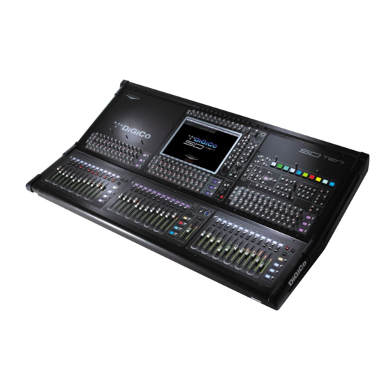
1.1 Introduction The Digico SD10 consists of a worksurface with an onboard audio engine and a range of onboard inputs and outputs. This can be connected to multiple Input/Output Rack Units by MADI links or optical fibre (optionally) which carry all the audio input and output signals. -
Page 12: Before You Start
Chapter 1 - Getting Started 1.3 Before You Start There are certain general operating principles and terms that should be understood before continuing to use this manual. Please read this chapter carefully before proceeding. 1.3.1 Worksurface Layout.............. Centre Section Light Assignable Rotary Scrollers USB Port Controls... -
Page 13: Screen Assignment
1.3.2 Screen Assignment ............... The SD10 touchscreen is used to access many of the console's functions. There are 4 possible views that can be seen on this screen - Left section - Centre section - Right section - Master screen... -
Page 14: Layers And Banks
1.3.3 Layers and Banks ..............The SD10's worksurface is divided into Layers and Banks. Each Bank contains twelve channels, and the channels which are currently active on the control surface are defined using the fader bank and bank layer buttons to the right of the Channel Strip section’s faders:... -
Page 15: The Assigned Channel
Chapter 1 - Getting Started 1.3.5 The Assigned Channel ............One of the channels in the Channel Strip panel is displayed in gold, indicating that it is currently the Assigned Channel. This means that it has been assigned to the worksurface controls and can be configured in detail, as described below. To Assign a channel, touch anywhere in the channel on the screen (except the Aux Send area). -
Page 16: Other Centre Section Controls
1.3.8 Channel Types ..............The signal flow of the SD10 is best understood in terms of the four channel types contained within it, shown below. Each channel type offers full signal processing capabilities. As a summary, the four channel types are as follows: Input channels bring signals into the console to be mixed and sent to aux and group busses. -
Page 17: Hardware Configuration
The SD10 worksurface has 8 analogue I/O and 8 AES I/O on its rear panel and remote I/O racks are available in several formats. These racks can be connected to the console with 2x 100M high specification 75Ohm coaxial cables fitted with BNC connectors, or optical fibre. -
Page 18: Audio I/O Panel
Chapter 1 - Getting Started 1.4.2 Audio I/O Panel..............The Audio I/O window is used to configure the physical I/O connected to the SD10, including configuring and naming the sockets of the cards installed in racks, and the setting of Pads and phantom power. - Page 19 Chapter 1 - Getting Started Rack Connections With a Rack selected in the left hand port selection list, the window will change to look something like the image below, depending on the cards installed in the connected rack. The graphic shows the 14 available cards/slots, 7 input & 7 output. In order to use the rack, the on-screen contents of the rack must match the cards physically installed in the rack connected.
- Page 20 Standard MADI Connections If you have a standard MADI connection (not a DiGiCo Rack) to your SD10, you can set the SD10 to display the MADI with generic signal names, i.e. MADI 1, MADI 2.. etc. through to MADI 56 instead of the usual rack style names. The naming does not affect the signal, but makes routing signals easier.
Need help?
Do you have a question about the SD10 and is the answer not in the manual?
Questions and answers