Table of Contents
Advertisement
Quick Links
Advertisement
Table of Contents

Related Manuals for Cypress OTT-2100


Summary of Contents for Cypress OTT-2100
- Page 1 Handheld OSDP COMSET Tool OTT-2100 Product Manual OTT-2100_220726 Cypress Integration Solutions 35+ Years of Access Control Ingenuity CypressIntegration.com Page 1 2022 Cypress Computer Systems 1778 Imlay City Road, Lapeer, MI 48446 800-807-2977 ©...
-
Page 2: Overview And Specifications
OSDP reader or other Peripheral Device without a tablet device, laptop PC, desktop PC, or access controller. A technician can use the OTT-2100 to set the address and baud rate of OSDP readers before they are installed in the field, or after installation. -
Page 3: Table Of Contents
Cypress OTT-2100 Manual - Table of Contents Table of Contents Topic Page Overview and Specifications Physical Features Dimensions Wiring Diagram: COMSET Mode Wiring Diagram: Listening Mode Wiring Diagram: Firmware Update Mode Status LEDs DIP Switches Address DIP Switch Tables 11-13... -
Page 4: Physical Features
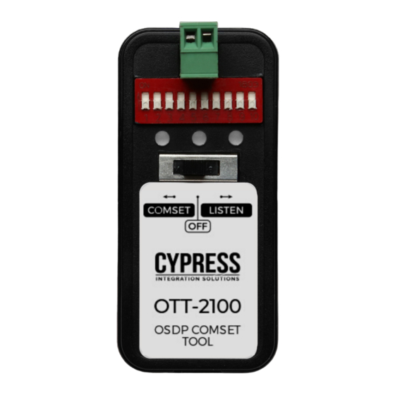
Cypress OTT-2100 Manual - Physical Features DIP Switches Status LEDs Product Label OSDP Port Power/Mode Switch (Removable screw terminal block) Serial Number Label Battery Compartment Page 4... -
Page 5: Dimensions
Cypress OTT-2100 Manual - Dimensions 0.975 inches 3.00 inches thick 1.375 inches Page 5... -
Page 6: Wiring Diagram: Comset Mode
Cypress OTT-2100 Manual - Wiring Diagram: COMSET Mode OSDP Data Lines OSDP Reader DC Power Supply Power Ground Page 6... -
Page 7: Wiring Diagram: Listening Mode
Cypress OTT-2100 Manual - Wiring Diagram: Listening Mode OSDP Access Control Panel RS485 A RS485 B OSDP Data Lines OSDP Reader DC Power Supply Power Ground Page 7... -
Page 8: Wiring Diagram: Firmware Update Mode
Cypress OTT-2100 Manual - Wiring Diagram: Firmware Update Mode OSDP Data Lines OSDP Access Control Panel RS485 A RS485 B Page 8... -
Page 9: Status Leds
LED 3 LED 2 The OTT-2100 has three RGB LEDs that show the status of the device. The LED displays are different, depending on the operating mode the unit is in. There are LED tables showing the states and meanings of the three LEDs in each of the operating mode sections of this manual. When the device is powered on in any mode, LED 2 (center) will display the power up sequence. -
Page 10: Dip Switches
Baud Rate Select The OTT-2100 has a 10 position DIP switch bank that is used to select the OSDP address and the baud rate that the OTT-2100 will configure in the connected OSDP reader or PD. The DIP switch is ON when the switch is pushed away from the number on the DIP switch bank, or towards the 2- pin header/connector. -
Page 11: Address Dip Switch Tables
Cypress OTT-2100 Manual - Address DIP Switch Tables Address Address X = ON X = ON Page 11... - Page 12 Cypress OTT-2100 Manual - DIP Switch Tables (continued) Address Address X = ON X = ON Page 12...
- Page 13 Cypress OTT-2100 Manual - DIP Switch Tables (continued) Address X = ON Page 13...
-
Page 14: Operating Modes: Comest Mode
The OTT-2100 has an OSDP polarity switching feature, which allows the device to communicate with the reader or PD no matter the polarity of the connected OSDP lines. When the OTT-2100 is connected to a PD and is powered on in COMSET Mode, it will do the following: 1. - Page 15 Cypress OTT-2100 Manual - Operating Modes: COMSET Mode (cont.) COMSET Mode LED Table LED State Meaning LED 1 Flashing Green Communicating with the PD LED 1 Flashing Blue Searching for PD LED 1 Solid Red Low battery voltage LED 2 Solid Green PD’s address and baud rate have been set to the selected values...
-
Page 16: Operating Modes: Listening Mode
2. Connect two OSDP data lines used by the ACU and PD to the removable screw terminal block on the OTT-2100. The polarity of the OSDP data lines does not matter, as the polarity switching feature will allow communication regardless of the polarity. - Page 17 Cypress OTT-2100 Manual - Operating Modes: Listening Mode (cont.) Listening Mode LED Table LED State Meaning LED 1 Flashing Green ACU sent a command to the PD while in a Secure Channel session (encrypted) LED 1 Flashing Blue ACU sent a command to the PD while in a Clear Channel session (unencrypted)
-
Page 18: Operating Modes: Firmware Update Mode
Firmware Update Mode. 4. LED 1 will be flashing red while it is waiting to be polled by the ACU. Once the OTT-2100 is being polled by the ACU, LED 1 will be flashing green if in a Secure Channel session or flashing blue is in a Clear Channel session. -
Page 19: Osdp Terminology
Cypress OTT-2100 Manual - OSDP Terminology This section lists and defines in general terms OSDP terminology used in this manual. Access Control Unit (ACU): Typically the access controller, the ACU is the device on the OSDP bus that controls the PDs. The ACU only sends commands to the PDs and waits for replies.
Need help?
Do you have a question about the OTT-2100 and is the answer not in the manual?
Questions and answers