Table of Contents
Advertisement
Available languages
Available languages
Quick Links
ASME A112.18.1 / CSA B125.1
Models
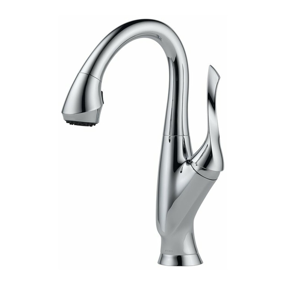
63052LF & 63952LF
Series
®
BELO
Write purchased model number here.
WARNING: THIS FAUCET IS NOT TO BE USED WITH PORTABLE DISHWASHERS!
You may need the following tools:
1/8"
For easy installation of your Brizo
faucet you will need:
READ ALL the instructions
completely before beginning.
READ ALL warnings, care, and
maintenance information.
77522 Rev. A
77522 Rev. A
PULL-DOWN KITCHEN
AND BAR / PREP FAUCETS
®
1
08/16/13
Advertisement
Table of Contents

Related Manuals for Brizo BELO 63052LF


Summary of Contents for Brizo BELO 63052LF
- Page 1 Write purchased model number here. WARNING: THIS FAUCET IS NOT TO BE USED WITH PORTABLE DISHWASHERS! You may need the following tools: 1/8" For easy installation of your Brizo ® faucet you will need: READ ALL the instructions completely before beginning.
- Page 2 Limited Warranty on Brizo Faucets Parts and Finish All parts (other than electronic parts and batteries) and finishes of this Brizo ® faucet are warranted to the original con- sumer purchaser to be free from defects in material and workmanship for as long as the original consumer purchaser owns the home in which the faucet was first installed or, for commercial users, for 5 years from the date of purchase.
-
Page 3: Hose Installation
Bend Hose Installation Insert hose (1) into and through spout sub-assembly (2). hose near wand as shown. 77522 Rev. A... -
Page 4: Spout Assembly
Spout Assembly Verify friction washer (1), spout clip (2) and spout ring (3) are present on spout assembly. 77522 Rev. A... - Page 5 Spout Assembly (Continuation) Insert hose (1) through guide in hub Align button (1) on spout clip with hole and out through mounting shank (2). in hub (2), then insert spout into hub. Use back-and-forth motion to insert spout assembly into hub until clip button slips into hole.
- Page 6 Faucet Installation - Center Mount Remove adhesive backing on trim Push hose (1) partially up into mounting ring gasket (1) and press into place shank (2). Install the mounting bracket on trim ring (2). Place trim ring on (3) and nut (4) onto the mounting shank bottom of spout hub.
- Page 7 Optional Optional Escutcheon Installation For optional installations using the 10" two 1/4-20 studs (4), nuts and washers escutcheon, order RP49588 (specify finish) (5), bracket (6) with nut and wrench (7). not supplied. Replace the trim ring with the The wrench provided is designed to 10"...
-
Page 8: Water Line Connections
Water Line Connections Ensure all fittings and end connections connect fitting (1), open both supply are free of debris. Faucet fittings (1) valves (2) and turn faucet valve on by are 3/8" compression, with ends operating handle (3) for one minute. colored red for hot and blue for cold. - Page 9 Custom Fit Connections NOTICE: If you determine the PEX supply turn faucet valve on by operating handle (3) for one minute. Important: This flushes tubing for this faucet is too long and must be shorter to create an acceptable away any debris that could cause installation, be sure to read the instruc- damage to internal components.
-
Page 10: Correct Method
Custom Fit Connections - Plastic Sleeve Installation Instructions Correct method 1. Identify desired length of tube (1). Leave 1" - 2" of extra length to allow for easier installation and cut tube. Ensure cut is straight and burr free. 2. Slide nut (2) and plastic sleeve (3) onto cut tube. Ensure sleeve is oriented as shown. - Page 11 Sprayer Hose Connections Insert hose end (1) through hose weight assembly (2). (1) into adapter. Insert check-valve adapter (1) into Rotate arms of adapter (1) to secure pull-out hose fitting (2). Ensure assembly to pull-out hose and faucet weight does not slide off hose. outlet tube.
- Page 12 Unlock Lock Faucet Inspection and Operation Sprayer will lock into position when (1). Pull the hose assembly (2) out of brought into proximity of the spout the spout. Be sure to hold the end of the sprayer down into the sink and turn either pulling directly out from the spout faucet handle (3) to the mixed position or by twisting 90°...
- Page 13 Setting The Handle Limit Stop (Optional) because it limits the amount of hot water in the mix; however, this handle limit stop will handle limit stop that has two positions. not always prevent scalding because it does Position 1, to the left, allows full handle not compensate for incoming pressure or motion (the full range between “all cold”...
-
Page 14: Maintenance
Maintenance Backflow Protection System ® Faucet pull-down spout If faucet leaks from under handle: Remove handle and ensure cap (1) is tight. that has been tested to be in compliance If leak persists with ASME A112.18.3 and SUPPLIES. Replace valve cartridge (2). ASME A112.18.1 / CSA B125.1. - Page 15 Escriba aquí el número del modelo comprado. ADVERTENCIA: ¡SESTA LLAVE NO SE DEBE UTILIZAR CON MAQUINAS LAVAPLATOS PORTATILES! Usted puede necesitar: 1/8" Para instalación fácil de su llave Brizo usted necesitará: ® LEER TODAS las instrucciones completamente antes de empezar. LEER TODOS los avisos, cuidados, e información de mantenimiento.
- Page 16 1-877-345-BRIZO (2749) customerservice@deltafaucet.com customerservice@mascocanada.com La prueba de compra (recibo original) del comprador original debe ser disponible a Delta Faucet Company para le aplica sólo a las llaves de agua de Brizo ® © 2013 Masco Corporación de Indiana 77522 Rev. A...
-
Page 17: Instalación De La Manguera
Doble Instalación de la Manguera Introduzca la manguera (1) en y a mango del rociador (2). surtidor (2). Para permitir un ensamble más fácil, doble la manguera cerca del mango como se muestra. 77522 Rev. A 08/13/13... - Page 18 Ensamble de Surtidor (3), están presentes en el ensamble del surtidor. 77522 Rev. A...
- Page 19 Ensamble de Surtidor (Continuación) Introduzca la manguera (1) por la Alinee el botón (1) en el gancho del la espiga de instalación (2). (2), luego introduzca el surtidor en el para introducir el ensamble del surti- para asegurar un funcionamiento suave.
- Page 20 Instalación de la Llave de Agua – Instalación de Centro hacia arriba en la espiga de instalación (2). Instale el soporte de la instalación (3) y la y oprima en su sitio en el aro de tuerca (4) en la espiga de instalación usando la llave de tuercas (5).
- Page 21 Opcional Instalación de una Chapa Opcional Para instalaciones opcionales usando la pernos de 2 1/4-20 (4), las tuercas y chapa o chapetón de 10”, ordene la pieza arandelas (5), el soporte (6) con la tuerca y la llave de tuercas (7). La llave incluye.
- Page 22 Conexiones a la Línea de Agua conexión rápida de la llave de agua (1) residuos. Los accesorios (1) son de y abra por un minuto ambas válvulas compresión de 3/8”, con los extremos Importante: Esto limpia cualquier residuo que pudiera causar daño a Nota: La los componentes internos.
- Page 23 Conexiones Especiales rápida de la llave de agua (1) y abra AVISO: Si usted determina que la tubería por un minuto ambas válvulas (2) y PEX para el suministro de agua para esta llave de agua es muy larga y debe recortarse para crear una instalación Importante: Esto limpia cualquier aceptable, asegúrese leer las instruccio-...
- Page 24 Instrucciones para la Instalación del la Manga Plástica Método Correcto 1” – 2” de soltura para una instalación más fácil y sin rebabas. 2. Resbale la tuerca (2) y la manga plástica (3) sobre el tubo cortado. Asegure la manga se orienta según lo demostrado.
- Page 25 Conexiones de la Manguera con Rociador Introduzca el extreme de la manguera Introduzca el empalme de conexión (1) por el ensamble de la pesa de la rápida en el extremo de salida de agua manguera (2). del grifo (1) en el adaptador. Introduzca el adaptador de la válvula de retención (1) en el accesorio tubo de salida de la llave de agua.
- Page 26 abrir cerrar Inspección de la Llave de Agua / Grifo y Funcionamiento Abra los suministros de agua caliente y cuando se acerca al imán del surtidor. El rociador puede sacarse halándolo directamente hacia fuera del surtidor o extremo de rociador hacia el fregadero y la posición mixta por un minuto.
- Page 27 Fijando la parada de límite de la manija (opcional) a la posición 2 puede ayudar a prevenir limitar la temperatura. La posición 1, a la agua caliente en la mezcla; sin embargo, agua no siempre prevendrá escaldaduras caliente”). La fábrica preselecciona la llave de agua (grifo) a la posición 1.
-
Page 28: Mantenimiento
1/8" Mantenimiento Sistema de protección contra el contraflujo Si la llave de agua tiene una filtración por debajo de la manija: Su llave de agua tipo deslizable Delta tiene un sistema de protección contra el está apretada. Si la filtración persiste – CIERRE LOS ASME A112.18.3 y ASME A112.18.1 / cartucho de la válvula (2). - Page 29 MISE EN GARDE : NE PAS RACCORDER DE LAVE-VAISSELLE MOBILES À CE ROBINET! Articles dont vous pouvez avoir besoin: 1/8 po Pour installer votre robinet Brizo facilement, vous devez: ® LIRE TOUTES les instructions avant LIRE TOUS les avertissements ainsi 77522 Rev.
- Page 30 Pièces de rechange - - - - - - - - - - - - - - - - - - - - - - - - - - - - - - - - - - - - - - - - - - - - - - - - - - - Pages 1 5 e t 1 6 ® Garantie limitée des robinets Brizo Pièces et finis ®...
- Page 31 courbez Installation du flexible et faites-le glisser de part en part du bec (2). comme le montre la figure. 77522 Rev. A...
- Page 32 Installation du bec bec (3) se trouvent sur le bec. 77522 Rev. A...
- Page 33 Installation du bec (suite) Faites correspondre le bouton (1) sur guide du porte-bec, puis dans la tige de montage (2). porte-bec (2), puis introduisez le bec dans le porte-bec. Imprimez un mou- vement de va-et-vient au bec pour dans le trou. Faites pivoter le bec pour PRENEZ GARDE DE VOUS PINCER LES DOIGTS.
- Page 34 Installation du robinet – Montage dan le trou au centre de l’évier Introduisez le flexible (1) partiellement circulaire (1) et placez-le contre dans la tige de montage (2). Installez de finition contre le dessous du ou moins, placez la cale (6) fournie entre porte-bec.
- Page 35 Facultative Installation de la plaque de finition facultative de finition facultative de 10 po, comman- La clé fournie est conçue pour être utilisée avec une variété d’outils : ment vers le haut dans la tige de montage. tournevis à extrémité plate ou Phillips, clés, etc.
- Page 36 Branchement à la tuyauterie Placez un seau sous le raccord rapide (1), puis ouvrez les deux une minute. Important : Cette opération vise à évacuer les froide est bleue. Faites une boucle avec le débris qui pourraient abîmer Note : Le les composants internes.
- Page 37 Spéciaux Tuyauterie Branchement NOTIFICATION : Si le tube d’alimentation en PEX de ce robinet est trop long et une minute. Important : Cette opération doit être raccourci, lisez les instructions vise à évacuer les débris qui pourraient et prenez le temps de réfléchir. Vous abîmer les composants internes.
- Page 38 Instructions d’installations de le manchon en plastique Bonne méthode 3. Introduisez le tube dans le raccord (4). Le tube doit MISE EN GARDE : Si le manchon en plastique n’a pas été installé dans l’orientation correcte, le raccord peut se défaire et l’eau peut occasionner des dommages.
- Page 39 Branchement du flexible de la douchette Introduisez le raccord rapide du robinet dans la masselotte du flexible (2). (1) dans le raccord du flexible (2). la douchette et le flexible de sortie du libère du flexible. robinet. 77522 Rev. A...
- Page 40 déverrouiller Verrouiller Inspection et utilisation du robinet directement sur celle-ci ou tournez-la douchette en actionnant la gâchette (4) Serrez les raccords de nouveau au besoin, mais pas excessivement. fonctions seulement. Enfoncez le bouton 77522 Rev. A...
- Page 41 Plaçant l’arrêt de limite de poignée (facultatif) maximale de la manette ne constitue pas Pour modifier la position de la butée de température maximale de la manette : ture maximale de la manette au moment de 77522 Rev. A...
-
Page 42: Entretien
1/8 po Entretien Dispositif anti-siphonnage Si le robinet fuit par le dessous de la comporte un dispositif anti-siphonnage manette : aux normes ASME A112.18.3 et ASME A112.18.1 / CSA B125.1. Ce Si la fuite persiste, COUPEZ L’ARRIVÉE dispositif se compose de deux clapets D’EAU. - Page 43 RP50580▲ RP50576▲ (models 63052 & 63352) (model 63952) Spout Assembly Spout Assembly RP50582▲ (All Models) RP50583▲ Manette (model 63052 & 63352) Sprayer Assembly RP50585▲ (includes aerator) Set Screw, Ensamble de rociador O-Ring & Button (incluye el aireador) Presión, Anillo-O y Botón Vis de calage, bouton RP50577▲...
- Page 44 RP49589▲ Dispenser Assembly Ensamble del Dispensador Distributeur RP49640▲ Vase Only - Metal Sólo el recipiente - Metal RP21908 RP50578▲ Pump Body Assembly Bomba (includes base & Pompe gasket) Ensamble del Cuerpo RP50578▲ (incluye base y Body Assembly (includes base & Corps gasket) Ensamble del Cuerpo...
Need help?
Do you have a question about the BELO 63052LF and is the answer not in the manual?
Questions and answers