Table of Contents
Advertisement
Quick Links
Advertisement
Table of Contents

Subscribe to Our Youtube Channel
Related Manuals for Apex Digital AIC400 Series


Summary of Contents for Apex Digital AIC400 Series
- Page 1 AIC400 Series Alarm Annunciator AIC400 Series Alarm Annunciator User Manual (Ver. 4.2 / May 2019) 3-350 John Street, Thornhill, Ontario L3T 5W6 Phone: +1 289 597 APEX (2739) Toll Free: 1 866 776 2943 Email: info@APEXannunciator.com Web: www.APEXANNUNCIATOR.com...
-
Page 2: Technical Specification
AIC400 Series Alarm Annunciator Technical Specification: Size Variety Inputs The AIC400 Annunciators come in various sizes from The AIC400 supports all input types (Dry Contact, 4 to 48 windows. Each unit has also eight RGB LEDs Wet Inputs, Normally-Closed, Normally-Open). - Page 3 AIC400 Series Alarm Annunciator Adjustable light and sound Redundant Power Supply (option) The LEDs’ brightness and the integral Audible volume The AIC400 can be equipped with integral redundant are adjustable from 10% to 100% by the built-in power supplies even with different voltage levels in pushbuttons and via the ALCON software as well.
- Page 4 AIC400 Series Alarm Annunciator Alarm Sequences Event Recording (optional) All the standard alarm sequences are supported by In order to track the sequence of events in a process, the AIC400 as defined in the ISA S18.1/1979 the AIC400 can be supplied with integral Event...
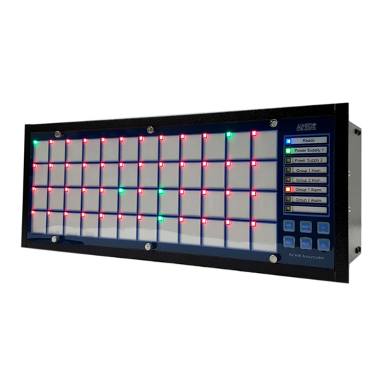
- Page 5 AIC400 Series Alarm Annunciator Alarm AIC400 Front View windows/ indicators Alarm Labels 1-48 Window Window System Ready address: address: indicator Power Source 1 status indicator Window Window Power Source 2 address: status indicator address: Group1 Horn Indicator Group2 Horn Window...
- Page 6 AIC400 Series Alarm Annunciator Alarm Windows/Indicators: Each 24mm x 22mm window is equipped with a supper bright, Multi-color LED. The standard system supports Red, Green and Yellow (RGY set) LED colors. User can assign a color to each LED state according to the application requirement for Normal and Abnormal conditions as shown below.
-
Page 7: Power Supply Wiring
AIC400 Series Alarm Annunciator Power Supply Wiring The standard AIC400 is designed to accept Nominal 24VDC (22V to 26V) power supply. Other voltages including 90-260VAC/DC (Universal) can be also selected at the time of order. Integral redundant power supplies are also available as an option at the time of order. There are two power indicator LEDs to show the status of each power supply. -
Page 8: Alarm Inputs
AIC400 Series Alarm Annunciator Alarm Inputs Inputs are optically isolated up to 2000VAC. These Inputs are arranged in groups of four with one common connection per group. Connectors 1 to 4 are assigned to each Input and the fifth connector is assigned to the common of theses Inputs. - Page 9 AIC400 Series Alarm Annunciator Alarm Inputs Wiring Diagram The wiring diagram of Dry Contact and Powered Inputs are shown below. Input Connectors Input Connectors In 1 In 1 In 2 In 2 In 3 In 3 In 4 In 4...
- Page 10 AIC400 Series Alarm Annunciator Common Relays and Auxiliary Relays Common Relays Connectors Auxiliary Relays Connectors Common Output Output Relays Connector 1 Connector 12 Com. Com. Com. Com. Com. Com. Com. Com. Com. Com. Com. Com. Common Relay Outputs The AIC400 provides up to four common relays. The contact rating of each relay is 1A@ 24VDC or 0.5A@ 125VAC.
- Page 11 AIC400 Series Alarm Annunciator Common Relays and Auxiliary Relays Individual Auxiliary Relays (optional) This option provides the user with a dry contact Inside the Annunciator (potential free contact) per alarm point for use with Com. Form C 3rd party devices. Both Normally Open and Normally Relay 1 Aux.
-
Page 12: Mechanical Installation
AIC400 Series Alarm Annunciator Mechanical Installation Panel (Flush) Mount Installation Panel Screw Type Flush-mounting Clamp For panel-mount installation, make a cut-out on your panel. The recommended cut-out dimensions are listed below. Insert the Annunciator inside the panel from the front opening and secure it with four mounting clamps from the back. -
Page 13: Alarm Sequences
AIC400 Series Alarm Annunciator Alarm Sequences AIC400 supports all ISA-18.1 Alarm sequences including: Manual Reset (Sequence Code M) - Manual Reset (M) P: Normal - Automatic Reset (A) S: Normal V: Off - Automatic Reset First Out (F3A) A: Silent... - Page 14 AIC400 Series Alarm Annunciator Alarm Sequences Auto Reset First Out (Sequence F3A) Manual Reset First Out (Sequence F2M-1) P: Normal P: Normal S: Normal S: Normal V: Off V: Off A: Silent A: Silent Subsequent Reset Subsequent First to to Abnormal...
- Page 15 AIC400 Series Alarm Annunciator Parameters programing by ALCON software The AIC400 is a fully programable Annunciator. Most of the parameter are configurable via ALCON that is an advanced configuration software. It allows the user to create, edit, and send the required configurations to the AIC400 Annunciators via USB port.
- Page 16 AIC400 Series Alarm Annunciator The AIC400 Annunciator comes with a flash drive. There are two EXE files in this folder (CDM21228_Setup.exe and ALCON.exe). 1 - Copy the APEX-Annunciator folder from the flash drive on your laptop. 2 - Run the CDM21228_Setup.exe. When the driver is successfully installed, then go to the next step.
- Page 17 AIC400 Series Alarm Annunciator ALCON Main Page The ALCON main page is shown below. You can find an instruction of each menu on the next page to see how to setup the parameters. (17)
- Page 18 AIC400 Series Alarm Annunciator Window Parameters setup - Under the “Tools” Menu (A), go to “Com Port” Menu and select the Com Port which is assigned to the Annunciator (the active Com Port is highlighted in the list). - Under the “Tools” Menu (A), go to “Baud Rate” menu and select 115200.
- Page 19 AIC400 Series Alarm Annunciator Common Parameters setup Press the ‘‘Common Parameters’ (S) button. the following menu will pop up: Press the Relay menus (1 to 4) and assign a function to each relay according to your requirements. Press the ‘Send Relays Configs’ button (U) to send the Relays’ configuration to the Annunciator.
- Page 20 AIC400 Series Alarm Annunciator Common Parameters setup Response Time Press the ‘Response Time’ button and select a time according to your application and then press the ‘Sent Response Time’ button. The most common time range is 10ms to 50ms. Auto Mute The Auto Mute function turns the internal and external audibles Off after a set time.
- Page 21 AIC400 Series Alarm Annunciator AIC400 Modules AIC400 AIC400 AIC400 CPU Module LED Master LED Unit AIC400 AIC400 AIC400 Power Supply Input Master Input Unit Module (21)
Need help?
Do you have a question about the AIC400 Series and is the answer not in the manual?
Questions and answers