Table of Contents
Advertisement
Quick Links
Advertisement
Table of Contents

Subscribe to Our Youtube Channel
Related Manuals for Vision Makrolite 4K


Summary of Contents for Vision Makrolite 4K
- Page 1 User guide Makrolite 4K digital microscope 2015...
- Page 2 www.visioneng.com/support Ultra HD digital video inspection system...
-
Page 3: Preface
Copyright © 2021 Vision Engineering Ltd., Galileo Drive, Send Road, Send, Woking, Surrey GU23 7ER, UK All Rights Reserved. Makrolite 4K is a registered trademark of Vision Engineering Ltd. The use of our trademarks is strictly controlled and monitored and any unauthorised use is forbidden. -
Page 4: General
Never use chemicals to clean coloured surfaces or accessories with rubberised parts. Use a specialist lens cloth to clean optical surfaces. Servicing Repairs may only be carried out by Vision Engineering-trained service personnel. Only original Vision Engineering spare parts may be used. Symbols used Warning! A potential risk of danger exists. -
Page 5: Environmental Considerations
EMC directive. If the equipment is used in a manner not specified by Vision Engineering Ltd in this user guide, the protection provided by the equipment may be impaired. -
Page 6: Table Of Contents
Important information Health & safety Electrical safety Illumination safety Environmental considerations Operator wellbeing Compliance statements SYSTEM EQUIPMENT Makrolite 4K core components Required parts ordered separately Additional parts for PC version Optional accessory (for non-PC version) CONFIGURATIONS Console Configuration PC Configuration COMPONENTS... - Page 7 CONTENTS SET-UP Console Configuration Camera connections Console controls Notes on console functions Image capture and video recording (option) PC Configuration with ViPlus Component layout and camera connections ViPlus software overview and camera controls Live image tools Captured image tools Calibration & measurement 4K Video recording (Blackmagic Media Express utility) SPECIFICATIONS Camera data...
-
Page 8: System Equipment
SYSTEM EQUIPMENT Makrolite 4K core components: Makrolite 4K camera 12V power supply 2m HDMI cable (4K) Ring-light Console (keypad) 2m Micro-USB cable (required with PC configuration only). M4 x 10 cap screws - 4pcs (for attaching camera to the stand) ... -
Page 9: Configurations
CONFIGURATIONS Console Configuration The Makrolite 4K’s HDMI port connects directly to a 4K monitor. Full, stand-alone, control is via a console/keypad. Controls include: zoom, autofocus/manual focus, aperture & exposure settings, gain, white balance, objective selection, screen size selection, image flipping, and access to 4 pre-sets buttons whereby all of these settings can be saved/loaded for rapid set-up. -
Page 10: Components
Monito Objective Ring-light Figure 3: Makrolite 4K and top panel connections Objective lenses Fitting the objective. Objectives can be fitted quickly and easily with the quick release mount; first push the objective up and back so that the back of the objective pushes against the mount/holder, then bring the front of the lens up until it clicks into place. -
Page 11: Ring-Light
Connect power lead to the ‘ring-light’ socket on the top panel of the Makrolite 4. Ring-light brightness is controlled using the dimmer control on the front of the Makrolite 4K. The ring-light may not be required with the bench-stand as this stand includes sub-stage and incident (overhead) lighting. -
Page 12: Stands
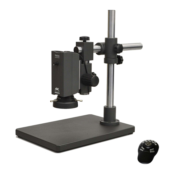
Stands Single arm boom stand The focus control of the stand attaches directly to the interface plate on the back of the Makrolite 4K camera with the 4 screws provided and using the holes indicated in the image (below right) -
Page 13: Double Arm Boom Stand
(part A in the image above right) to the stand (single screw) attach the incident light to the bracket (two screws) attach the adaptor plate (part B) to the interface plate on the Makrolite 4K using the two screw holes indicated in the image above attach the camera/adaptor plate (B) to the adaptor bracket (A) using the two screws holes indicated above. -
Page 14: Ergo Stand / Multi-Axis Stand
Figure 17: S416 adaptor holes for the S416 adaptor Fitting the S416 adaptor Use the 4 hex screws to attach the dovetail bracket and spacer to the interface plate of the Makrolite 4K using the screw holes indicated in the image above. -
Page 15: Console Configuration
The console (keypad) connects to the USB port labelled ‘Shuttle’ on the top panel of the Makrolite 4K. The monitor connects to the HDMI port using the 2m HDMI cable supplied. The Makrolite 4K is powered by the 12V DC supplier supplied. Once connected, switch on the camera and the monitor to complete the camera set up. -
Page 16: Console Controls
SET-UP Console controls The console (or keypad) has 15 Buttons. Some have two functions depending on whether the user makes a short press or a long press. The button functions are shown below. 2 Memory2 3 Memory3 7 Focus/Exposure 1 Memory1 4 Memory4 8 White balance 6 Mirror/Flip... -
Page 17: Notes On Console Functions
This option (M4K105) enables 4K image capture and 4K video recording without requiring a PC to be connected to the Makrolite 4K. It is connected by HDMI cables to the Makrolite 4K and to the monitor (see figures below). It is straightforward to use;... -
Page 18: Pc Configuration With Viplus
Figure 23: Component layout and Makrolite 4K The 2m micro USB cable (included) connects between micro-USB port on the top panel of the Makrolite 4K and a USB port on the PC. The HDMI cable (included) connects between the HDMI port on Makrolite 4K and the HDMI- input port of the capture device. -
Page 19: Viplus Software Overview And Camera Controls
Several versions of the ViPlus software are included on the USB stick supplied with ViPlus. The version to be installed for use with Makrolite 4K has the filename Blackmagic – display 4K. ViPlus provides control of Makrolite 4K; enabling adjustment of zoom, autofocus and camera settings. It is also used for measurement, annotation, image processing and data reporting. -
Page 20: Live Image Tools
SET-UP Live image tools Selecting ‘Video Command’ on the main menu allows access to the mirror and flip controls (see image below). This allows the live image to be flipped horizontally or vertically or both. Once set, this orientation will be the default setting. -
Page 21: Captured Image Tools
SET-UP Captured image tools As well as control of the Makrolite 4K camera, ViPlus also offers: Image capture (in JPEG, PNG, BMP or TIFF format) annotation tools including markers and measures, measurements tools such as distance, angle, diameter, area, import of CAD files for inspection with CAD juxtaposition, image processing tools such as colour inversion, shape detection, focus stacking (manual acquisition), overlays. -
Page 22: Video Recording (Blackmagic Media Express Utility)
SET-UP 4K Video recording (Blackmagic Media Expess Utility) Blackmagic capture cards are supplied with a software application for 4K video recording and 4K image capture. This is particularly useful because the Window 10 Camera app will not detect a camera connected via a capture card. -
Page 23: Specifications
SPECIFICATIONS Camera data Camera data Sensor CMOS 1/2,5” 8.51 mega pixels Image Ultra HD 2160p (3840 x 2160) Focus Autofocus or manual focus Camera output 4K 2160p/30fps Camera output on 4K 2160p/30fps on the PCI Express card computer Optical data Field of view Magnification zoom Working... -
Page 24: Appendices
USB3 4K capture devices. These devices are not supported. They are an alternative to a capture card and connect between the HDMI of the Makrolite 4K and a USB3 port on the PC. They are convenient because a PCIe or SFF slot is not required and so can be used with any suitable PC/laptop. -
Page 25: Appendix Ii: Viplus Calibration Procedure
To save the calibration, first change the calibration name in the ‘Cal Name’ field then select the icon. Manual Place a suitable calibration sheet (e.g. as supplied by Vision Engineering) containing at least one circle of a known dimension. Click on the Manual option. The system will place a rectangle in the display area. - Page 26 APPENDICES Drag the rectangle over the calibration circle and use the white point to change the size of the rectangle to fit the outside of the circle. Enter the required units for the calibration from the units drop down list (see main image right). ...
-
Page 27: Service Record
SERVICE System Serial Number: _______________ Date of Date of next Service Type Comments Company Signature Service Service www.visioneng.com/support Ultra HD digital video inspection system... -
Page 28: Warranty
Vision Engineering. Except as stated herein, Vision Engineering makes no other warranties, express or implied by law, whether for resale, fitness for a particular purpose or otherwise. Further, Vision Engineering shall not under any circumstances be liable for incidental, consequential or other damages. -
Page 29: Contacts
Tel: +49 (0) 8141 40167-0 Email: generalinfo@visioneng.com Tel: +1 (860) 355 3776 Email: info@visioneng.de Email: info@visioneng.com Vision Engineering Ltd. (Italia) Nippon Vision Engineering Via G. Paisiello 106 Vision Engineering Ltd. (France) (Japan) 20092 Cinisello Balsamo MI, ZAC de la Tremblaie, 272-2 Saedo-cho, Tsuduki-ku, Italia Av.
Need help?
Do you have a question about the Makrolite 4K and is the answer not in the manual?
Questions and answers