Table of Contents

Related Manuals for Boss 356


Summary of Contents for Boss 356
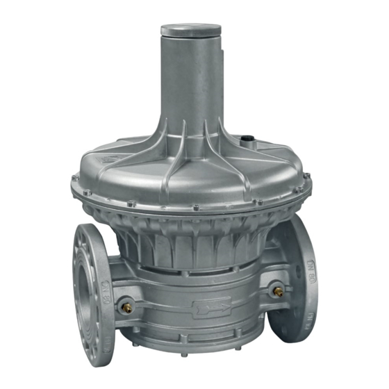
- Page 1 GAS PRESSURE REGULATOR P1 max 500 mbar DN15 - DN 20 - DN 25 - DN 32 - DN 40 - DN 50 DN 65 - DN 80 - DN 100 CE-51CL4012/ED01 II 2G - II 2D MADE IN ITALY EC approval according to EN 88-1, compliant with Regulation (EU) 2016/426...
- Page 2 INDEX pag. English ................................ 3 Drawings ..............................10 Dimensions (table 1) .............................13 Regulation spring data (table 3) ........................14 Diagram ...............................15...
-
Page 3: General Information
1.0 - GENERAL INFORMATION This manual shows you how to safely install, operate and use the device. The instructions for use ALWAYS need to be available in the facility where the device is installed. ATTENTION: installation/maintenance needs to be carried out by qualified staff (as explained in section 1.3) by using suitable personal protective equipment (PPE). -
Page 4: Technical Data
2.0 - TECHNICAL DATA • Use : non-aggressive gases of the three families (dry gases) • Ambient temperature (TS) : -15 ÷ +60 °C • Maximum operating pressure : 500 mbar • Class : A (P2 ± 15%) • Mechanical resistance : Group 2 (according to EN 13611) •... - Page 5 3.2 - INSTALLATION (see example in 3.4) Threaded devices: • Assemble the device by screwing it, with the due seals, onto the plant with pipes and/or fittings whose threads are consistent with the connection being attached. • Do not use the neck of the top cover (4) as a lever to help you screw it on, only use the specific tool; •...
- Page 6 8. Vent valve 3. Gas filter 9. Ball valve 4. OPSO shut off valve 10. Gas detector 5. 356 BOSS pressure regulator 11. Remote jerk ON/OFF valve lever control 6. Relief valve 12. Expansion joint/anti-vibration mount discharge in open air...
-
Page 7: First Start-Up
4.0 - FIRST START-UP Before commissioning, verify that: • all of the instructions on the rating plate, including the direction of flow, are observed; • the holes of the dust cap (6) are not clogged. • IMPORTANT: The leak test of the piping must be performed while avoiding to subject the membrane of the regulator (therefore, the downstream pipe section) to a pressure higher than 300 mbar. -
Page 8: Maintenance
5.0 - MAINTENANCE • Before carrying out any dismantling operation on the device, make sure that there is no pressurised gas inside. Check the condition of the filtering element (21) as follows* • Loosen the fastening screws (17) and very carefully remove the bottom cover (16) from the body (11); •... -
Page 9: Transport, Storage And Disposal
Lodge Way House, Lodge Way, 8.0 - RATING PLATE DATA Harlestone Road, Northampton NN5 7UG. Mod.: DN 50 BOSS 356 CODE: 35501293 The rating plate data (see example provided here) includes the following: P1 max: 500 mbar TS: -15+60 °C 13-23 mbar •... - Page 10 fig. 1 Threaded connections in line DN 15 - DN 20 - DN 25...
- Page 11 fig. 2 Threaded connections in line DN 32 - DN 40 - DN 50...
- Page 12 fig. 3 Flanged connections DN 65 - DN 80 - DN 100...
- Page 13 fig. 1, 2 and 3 9. Working membrane 18. Bottom cover sealing O-Ring 1. Closing cap 10. Centre pin (on DN 15-20-25 obturator pin) 19. Obturator 2. Adjustment screw P2 11. Body 20. Compensation membrane 3. Calibration spring 12. Sensor tube 21.
- Page 14 Table 3 Regulation spring data dimensions in mm (d x De x Lo x it) Spring code Connections Setting (mbar) MO-0402 1,5x29x85x10 9 ÷ 28 MO-0500 1,6x29x115x12 18 ÷ 40* MO-0825 2,2x29x100x12 DN 15 - DN 20 - DN 25 40 ÷...
- Page 15 Capacity diagram Diagram calculated with P1 = 50 mbar and regulator set out of service dv = density relative to the air 1) methane 2) air 3) town gas 4) lpg...
- Page 16 We reserve the right to any technical and construction changes. Registered Office: Travis Perkins PLC, Lodge Way House, Lodge Way, Harlestone Road, Northampton NN5 7UG. Telephone Number: 0116 245 5500 www.bssindustrial.co.uk - inquiries@bssgroup.com...
Need help?
Do you have a question about the 356 and is the answer not in the manual?
Questions and answers