
Subscribe to Our Youtube Channel
Related Manuals for Boss DN 15


Summary of Contents for Boss DN 15
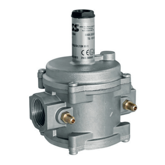
- Page 1 GAS PRESSURE REGULATOR DN15 - DN 20 - DN 25 CE-51AQ647/ED01 MADE IN ITALY EC approval according to EN 88-1, compliant with Regulation (EU) 2016/426...
- Page 2 INDEX pag. English ............................... 3 Drawings ..............................14 Dimensions (table 2) ............................ 16 Regulation spring data (table 3) ........................17 Diagram ..............................18...
-
Page 3: General Information
1.0 - GENERAL INFORMATION This manual shows you how to safely install, operate and use the device. The instructions for use ALWAYS need to be available in the facility where the device is installed. ATTENTION: installation/maintenance needs to be carried out by qualified staff (as explained in section 1.3) by using suitable personal protective equipment (PPE). -
Page 4: Qualified Staff
1.3 - QUALIFIED STAFF These are people who: • Are familiar with product installation, assembly, start-up and maintenance; • Know the regulations in force in the region or country pertaining to installation and safety; • Are trained in first aid. 1.4 - USING NON-ORIGINAL SPARE PARTS •... -
Page 5: Technical Data
• Mechanical resistance : Group 2 (according to EN 13611) • Rp threaded connections in line : (DN 15 - DN 20 - DN 25) according to EN 10226 • NPT threaded connections : request feasibility • In compliance with : Regulation (EU) 2016/426 (Appliances burning gaseous fuels) 2.1 - MODEL IDENTIFICATION... -
Page 6: Commissioning The Device
3.0 - COMMISSIONING THE DEVICE 3.1 - OPERATIONS PRIOR TO INSTALLATION • It is necessary to close the gas upstream of the device prior to installation; • Check that the line pressure IS WITHIN the P1 range indicated on the label of the product and that IT IS NOT HIGHER than the maximum value;... - Page 7 3.2 - INSTALLATION (see example in 3.4) • Assemble the device by screwing it, with the due seals, onto the plant with pipes and/or fittings whose threads are consistent with the connection being attached. • Do not use the neck of the top cover (3) as a lever to help you screw it on, but only use the specific tool; •...
- Page 8 7. Pressure gauge and relative button 2. Jerk ON/OFF valve 8. Gas detector 3. Gas filter 9. Remote jerk ON/OFF valve lever control 4. OPSO shut off valve 10. Expansion joint/anti-vibration mount 5. 356 BOSS pressure regulator discharge in open air 6. Relief valve...
-
Page 9: First Start-Up
4.0 - FIRST START-UP Before commissioning, verify that: • all of the instructions on the rating plate, including the direction of flow, are observed; • the small hole of the top cover (3) is not obstructed. • IMPORTANT: The leak test of the piping must be performed while avoiding to subject the membrane of the regulator (therefore, the downstream pipe section) to a pressure higher than 200 mbar. - Page 10 4.2 - ADJUSTING THE OUTLET PRESSURE Before starting the system, make sure that the spring supplied with the regulator is suitable for the desired adjustment pressure. The outlet pressure P2 (unless specifically requested) is factory set with the top cover (3) positioned as shown in and with the adjustment screw (2) set approximately at the minimum calibration value.
-
Page 11: Maintenance
5.0 - MAINTENANCE • Before carrying out any dismantling operation on the device, make sure that there is no pressurised gas inside. To check the status of the filter element (7)* • Loosen the fastening screws (8) and very carefully remove the bottom cover (10) from the body (5); •... -
Page 12: Transport, Storage And Disposal
fig a: Cover without bottom cover The filter element must be placed inside these guides Guides for filter element 6.0 - TRANSPORT, STORAGE AND DISPOSAL 7.0 - WARRANTY • During transport the material needs to be handled with care, The warranty conditions agreed with the manufacturer at the avoiding any impact or vibrations to the device;... -
Page 13: Rating Plate Data
8.0 - RATING PLATE DATA Lodge Way House, Lodge Way, Harlestone Road, Northampton NN5 7UG. The rating plate data (see example provided here) includes the following: Mod.: DN 20 BOSS 356 CODE: 35501227 P1: 200-300 mbar TS: -15+60 °C P2: 16-60 mbar CE-51AQ647/ED01 CI.A Gr.2 EN 88-1... - Page 14 1 DN 15 - DN 20 - DN 25...
- Page 15 fig. 1 1. Closing cap 2. Adjustment screw P2 3. Top cover 4. Working membrane/centre pin 5. Body 6. Pressure test nipple (optional) 7. Filter element 8. Bottom cover clamping screws 9. Obturator 10. Bottom cover 11. Bottom cover sealing O-Ring 12.
- Page 16 Table 2 Overall dimensions in mm Connections in line B=(D+E) Rp DN 15 - Rp DN 20 - Rp DN 25 40,5 111,5 The dimensions are provided as a guideline, they are not binding...
- Page 17 13,7 ÷ 30 up to 100 MO-0210 1,3x17x70x11 20 ÷ 60 up to 100 MO-0213 1,3x17x55x8 16 ÷ 30 100÷200 MO-0210 1,3x17x70x11 DN 15 20 ÷ 70 100÷200 MO-0210 1,3x17x70x11 16 ÷ 60* 200÷300 MO-0210 1,3x17x70x11 16 ÷ 60 300÷400 MO-0210 1,3x17x70x11 16 ÷...
- Page 18 Capacity diagram of regulators without filter Diagram calculated with P1 = 50 mbar and regulator set out of service dv = density relative to the air 1) methane 2) air 3) town gas 4) lpg dv = 0,65 dv = 1 dv = 0,47 dv = 1,67...
- Page 19 NOTES...
- Page 20 We reserve the right to any technical and construction changes. Registered Office: Travis Perkins PLC, Lodge Way House, Lodge Way, Harlestone Road, Northampton NN5 7UG. Telephone Number: 0116 245 5500 www.bssindustrial.co.uk - inquiries@bssgroup.com...
Need help?
Do you have a question about the DN 15 and is the answer not in the manual?
Questions and answers