
Subscribe to Our Youtube Channel
Related Manuals for Control Technology CTI 2554-A


Summary of Contents for Control Technology CTI 2554-A
- Page 1 CTI 2554-A FOUR CHANNEL HIGH SPEED COUNTER MODULE INSTALLATION AND OPERATION GUIDE Version 1.0 CTI Part #062-00223 2554-A IOG 13JUL2017...
- Page 2 C TI 2554-A Installation and Operation Guide...
- Page 3 Copyright © 2005 Control Technology Inc. All rights reserved. This manual is published by Control Technology Inc., 5734 Middlebrook Pike, Knoxville, TN 37921. This manual contains references to brand and product names which are tradenames, trademarks, and/or registered trademarks of Control Technology Inc. Siemens® and SIMATIC® are registered trademarks of Siemens AG.
- Page 4 C TI 2554-A Installation and Operation Guide...
-
Page 5: Preface
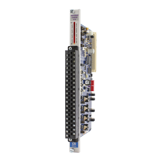
Chapter 4 covers module configuration. Chapter 5 is a PLC programming example. Chapter 6 is a guide to troubleshooting. Chapter 7 covers Quadrature Mode operation. Figure 1 The Model 2554-A Four-Channel High Speed Counter Module CTI 2554-A Installation and Operation Guide... - Page 6 C TI 2554-A Installation and Operation Guide...
-
Page 7: Usage Conventions
The CTI Model 2554-A High Speed Counter controls its four discrete outputs. If the PLC is switched from RUN mode to PROGRAM mode the module will continue to function as programmed and the outputs may be activated by the module. vi i CTI 2554-A Installation and Operation Guide... - Page 8 viii C TI 2554-A Installation and Operation Guide...
-
Page 9: Table Of Contents
4.4 Gate, Reset, and Output Jumpers......... . . 26 CTI 2554-A Installation and Operation Guide... - Page 10 CHAPTER 5. PLC Programming Example..........29 5.1 A Programming Example.
-
Page 11: Table Of Figures
Figure 32 Quadrature Wiring Example..........39 CTI 2554-A Installation and Operation Guide... - Page 12 C TI 2554-A Installation and Operation Guide...
-
Page 13: Chapter 1. Description
CHAPTER 1. DESCRIPTION The Model 2554-A Four-Channel High Speed Counter Module is a member of Control Technology's family of I/O modules compatible with the SIMATIC® 505 Series programmable controllers. 1.1 Theory of Operation The Model 2554-A High Speed Counter provides four channels which are designed to count input pulses and translate them into an equivalent digital word. -
Page 14: Mode 0 - Period Measurement (Microseconds)
1.2 Mode 0 - Period Measurement (microseconds) The period measurement mode provides good accuracy at low frequencies by counting the number of internal clock cycles between external input pulses. The internal clock is generated by a 1 MHz crystal oscillator. The data is reported to the PLC as microseconds and represents the period of the input signal. -
Page 15: Front Panel Description
The Blown Fuse LED will turn on if there is a blown fuse in any of the output circuits. This LED is common to all four channels. The replacement fuse type is listed in the module specifications in the back of this manual. CTI 2554-A Installation and Operation Guide... - Page 16 C TI 2554-A Installation and Operation Guide...
-
Page 17: Chapter 2. Mode 3 Operation
0-to-1 transition; a constant 0 or 1 or a transition from 1-to-0 does not cause ay action to take place. Where a bit is edge-sensitive it will be denoted, otherwise it is level-sensitive. CTI 2554-A Installation and Operation Guide... -
Page 18: Figure 5 Control Word Bit Assignments
Figure 5 Control Word Bit Assignments NOTE: The only edge-sensitive bits are bit 1 (turn output on or off), bit 6 (internal reset), and bit 7 (clear preset status latch). NOTE: Bit 5 is only looked at when a reset signal is active. It must be present before an edge-triggered reset comes active.You do not want to use this bit if the external reset is level-triggered because the preset will get toggled continuously with no user control over its final state when the reset signal is removed. -
Page 19: Loading Preset Values
If bit WY5:14 is a 1, the module ignores all other bits in WY5, and the whole WY8 word. The following figure illustrates channel addressing with bits WY5:15 and WY5:16. Figure 7 Selecting Input Channel for Target Presets CTI 2554-A Installation and Operation Guide... -
Page 20: Status Word
2.2 Status Word Under normal operation the count value is returned in the WX register for each input channel. When enabled a status word is reported. By setting WY:13 to a 1 (assuming WY5:14 is a 0), each channel can report status to the PLC instead of its current counter value. The first WX word (WX1 in this manual) corresponds to channel 1, and so on. -
Page 21: Preset Target Values
PLC or an external action to reset the counter. The maximum input frequency that auto reset can handle is 50 kHz; this is the aggregate sum for all the channels. CTI 2554-A Installation and Operation Guide... -
Page 22: Minimum Preset Target Values With Automatic Reset
NOTE: It is recommended that any channels not being used in a Mode 3 application be set to some other mode to relieve the microprocessor of continually checking for pulses. The latched preset status bit (WX:4) is only active in auto reset mode, and it can only be read if the WX word is returning status, not data (see WY:13). -
Page 23: Output Control
PLC scan so there is no way to specify the setup time. To know which preset the counter will resume comparing against, the user may read the preset status bit which the module can send to the PLC (see WX:6 and WY:13). CTI 2554-A Installation and Operation Guide... - Page 24 The internal/external reset of the channel output will turn the output on or off depending on which state is specified by the user (see WY:2). The internal reset (WY:6) is edge-sensitive. The external reset can be specified via jumpers to be either edge-sensitive (rising edge) or level-sensitive (high- active).
-
Page 25: Chapter 3. Installation
After discharging any static buildup, remove the module from the static bag. Do not discard the static bag. Always use this bag for protection against static damage when the module is not inserted into the I/O backplane. CTI 2554-A Installation and Operation Guide... -
Page 26: Inserting The Module Into The I/O Base
3.3 Inserting the Module into the I/O Base Insert the module into the I/O base by carefully pushing the module into the slot. When the module is fully seated in the slot and backplane connector, tighten the captive screws at the top and bottom to hold the module in place. -
Page 27: Connecting The Shield Wiring
3.4.1 Connecting the Shield Wiring Control Technology Inc. recommends that all wires be shielded twisted pair with a foil wrap shield and a separate drain wire and that they be installed in a metallic conduit. Use Belden cable 8761 or equivalent which contains a foil wrap shield and a separate drain wire. -
Page 28: Connecting To The Counter Inputs
3.4.2 Connecting to the Counter Inputs For (AC) sine wave counter inputs: Figure 11 (AC) Sine Wave Counter Inputs A. Wire counter "+" wire to "+" terminal B. Wire counter "-" wire to "-" terminal C. Wire Shield wire, if present, to external chassis ground D. -
Page 29: Connecting I/O Wiring
B. Wire counter "Collector" wire to "+" terminal C. Jumper "P" terminal on 2554-A to "+" terminal D. "-" terminal is not used E. Wire Shield wire, if present, to external chassis ground 3.4.3 Connecting I/O Wiring CTI 2554-A Installation and Operation Guide... -
Page 30: Wiring The Gate Inputs
3.4.4 Wiring the Gate Inputs: Before wiring an external device to the gate input ensure that the configuration jumpers JP100, 200, 300, and 400 are set for external gate operation. Wire the positive terminal of the controlling device to the (+) input on the Model 2554-A connector for the appropriate channel and the negative wire to the negative terminal. -
Page 31: Wiring The Outputs
NOTE: The output is protected by a zener diode and a 3 amp, 250V fuse. Replacement fuses are Littlefuse 2173.15 or Bussman GMA-3A. CTI 2554-A Installation and Operation Guide... -
Page 32: Checking Module Operation
3.5 Checking Module Operation First turn on the base power supply. If the module diagnostics detect no problems, the status indicator on the front of the module will light. If the status indicator does not light (or goes out during operation), the module has detected a failure. -
Page 33: Chapter 4. Configuring The Module
2. Selecting the proper input signal conditioning. 3. Selecting the proper counting mode for a counter configuration. 4. Selecting the proper gate, reset, and output settings. 5. Logging the configuration jumper settings for future reference. CTI 2554-A Installation and Operation Guide... -
Page 34: Selecting Counter Mode Or Quadrature Mode
4.1 Selecting Counter Mode or Quadrature Mode Jumper JP1 is used to select the operating mode of the module. When jumper JP1 is in the "Counter Mode" position, each of the 4 channels can be independently configured in one of the 4 count modes. When jumper JP1 is in the "Quadrature Mode"... -
Page 35: Input Signal Conditioning
(JP42, JP32, JP22, and JP12.) Default shipping configuration is positive pulse on all channels. Figure 21 Model 2554-A Input Signal Conditioning Jumpers CTI 2554-A Installation and Operation Guide... -
Page 36: Mode Select Switches And Jumpers
4.3 Mode Select Switches and Jumpers The mode select jumpers are used to set up the module for a specific counting function. It should be noted that each channel can be independently configured for a counting function (when not in quadrature mode). -
Page 37: Figure 23 Sw1 And Sw2 Settings
Figure 23 SW1 and SW2 Settings NOTE: When the module is configured for quadrature mode, channels 1 and 3 must be set for Mode 3. Channels 2 and 4 are "don't cares". CTI 2554-A Installation and Operation Guide... -
Page 38: Gate, Reset, And Output Jumpers
4.4 Gate, Reset, and Output Jumpers The following diagram shows the jumper locations for the gate, reset, and output control for each channel. Note that the "internal reset" is really just a storage position for the jumper. Internal reset capability is always available. The default shipping configuration is internal gate, internal reset, and normal outputs on all channel. -
Page 39: Figure 25 Model 2554-A Default Shipping Configuration
CTI 2554-A Installation and Operation Guide... -
Page 40: Chapter 5. Plc Programming Example
CHAPTER 5. PLC PROGRAMMING EXAMPLE 5.1 A Programming Example The following ladder program example is provided to demonstrate how the channel is reset and inhibited for counting, is loaded with a preset value, configured for a status word, output enabled on at preset 1 and off at preset 2, and configured for auto-reset. -
Page 41: Figure 26 Reset And Disable Input Counter Channels
(WY:11=1) and enable ch output (WY:12=1) to channels 2 through 4. Channel 1 receives 120 (0078H) = (same as above) plus WX=channel status (WY:13=1). So WX1 will report status and WX2/3/4 will report data. CTI 2554-A Installation and Operation Guide... -
Page 42: Figure 27 Control Word For Sample Application
Loading Preset Target Values: C TI 2554-A Installation and Operation Guide... - Page 43 On the next scan the BITC in rung 101 resets the clear preset status latch (WY:7) bit. The ladder logic counter keeps track of how many times the preset latch has been set. CTI 2554-A Installation and Operation Guide...
-
Page 44: Figure 28 Loading Preset Values For Channel 1
The final section of code demonstrates changing a preset value dynamically (while the counter is counting). When a preset has been reached 50 times, the preset 1 of channel 1 value will be changed to 4000. This happens in rung 131. The logic in rung 120 returns the WY control words to the same value as in rungs 25 and 34. - Page 45 CTI 2554-A Installation and Operation Guide...
- Page 46 C TI 2554-A Installation and Operation Guide...
-
Page 47: Chapter 6. Troubleshooting
No output Jumper disabled Enable with jumper Blown fuse Replace fuse Incorrect operation Not logged in PLC Use configure I/O function to verify module is logged as 4WX and 4WY memory locations CTI 2554-A Installation and Operation Guide... - Page 48 C TI 2554-A Installation and Operation Guide...
-
Page 49: Chapter 7. Quadrature Operation
The output can be turned on or off when the channel is reset, as is the case in regular counter mode. The output can be turned on or off when the preset has been reached, but this is polled in the background, so it is not quite as accurate as in regular counter mode. CTI 2554-A Installation and Operation Guide... -
Page 50: Quadrature Data Presentation
7.2 Quadrature Data Presentation Quadrature Mode requires an input channel for each A phase and B phase. As a result in Quadrature Mode two counter channels are available for applications. In Quadrature Mode the count value is returned in WX1 and WX3. Figure 35 PLC Interface 7.3 Wiring for Quadrature Mode Operation In quadrature encoders there are two output circuits labeled A and B. -
Page 51: Figure 32 Quadrature Wiring Example
Figure 38 Quadrature Wiring Example CTI 2554-A Installation and Operation Guide... - Page 52 C TI 2554-A Installation and Operation Guide...
-
Page 53: Specifications
Signal Input Isolation: 1500 VDC Channel-to-backplane 1500 VDC Channel-to-channel Control Output Specifications Outputs Per Module: Isolation: 500 VDC Channel-to-channel 1500 VDC Channel-to-backplane Output Voltage: 11 to 140 VDC Output Source Current Per Circuit: 1.5 Amps max CTI 2554-A Installation and Operation Guide... - Page 54 Maximum Surge Current: 3 Amps for 15 Sec "ON" State Voltage Drop: 0.3 V @ 2.0 Amps "OFF" State Leakage Current: 125 A @ 125 VDC Turn On Time: 1 Sec (nominal) Turn Off Time: 1 Sec (nominal) Control Input Specifications Inputs Per Channel: 2 (1 gate, 1 reset) Isolation:...
-
Page 55: Limited Product Warranty
CTI. Control Technology Inc. reserves the right to make changes to the Product in order to improve reliability, function, or design in the pursuit of providing the best possible Product. CTI assumes no responsibility for indirect or consequential damages resulting from the use or application of this equipment. - Page 56 C TI 2554-A Installation and Operation Guide...
-
Page 57: Repair Policy
Failure to observe static control precautions may void the warranty. For additional information on static control precautions, contact CTI's main office at 1-800-537-8398. CTI 2554-A Installation and Operation Guide... - Page 58 C TI 2554-A Installation and Operation Guide...
Need help?
Do you have a question about the CTI 2554-A and is the answer not in the manual?
Questions and answers