
Related Manuals for Kellfri 13-WC17H2

Summary of Contents for Kellfri 13-WC17H2
- Page 1 13-WC17H2 CHIPPER Read the operating instructions carefully before using the product! Operating instructions translated from Swedish...
- Page 2 Kellfri designs and supplies efficient, affordable machinery and components for forestry, ag- riculture, construction and gardening in Sweden, the rest of the Nordic region and Europe.
-
Page 3: Product Information
INTRODUCTION Thank you for choosing a product from Kellfri AB. Compliance with the safety instructions, operating man- ual and sound common sense will guarantee many years of enjoyment using the product. Kellfri’s equip- ment and products are aimed at self-employed farmers, horse enthusiasts and other country-dwellers who have stringent demands on performance. -
Page 4: Safety Instructions
If the safety instructions or instruction manual gets damaged or in any other way cannot be used, new copies may be ordered from: Kellfri AB, Munkatorpsgatan 6, SE-532 40 SKARA, Sweden. Tel: +46 511 242 50 The safety instructions can also be downloaded from Kellfri’s website: www.kellfri.co.uk... -
Page 5: Instructions For Emergency Situations
INSTRUCTIONS FOR EMERGENCY SITUATIONS In case of emergency, call 112 Always have a mobile phone or emergency phone available when working alone. A first-aid kit and fire extinguisher must be kept in an easily accessible location when carrying out any work, maintenance or service. -
Page 6: Warning Decals
4. The product numbers on the warning decals below are used to order the correct ones for your machine. 5. Warning decals can be ordered from Kellfri. Installation tips - Ensure the area is clean and dry and that the temperature is over 10°C. - Page 7 Think safety – work safer! 540 RPM 1000 RPM NOTE Missing or torn warning decals must be replaced with new ones, which are available from Kellfri. Table of contents...
-
Page 8: Specifications
SPECIFICATIONS 13-WC17H2 Wheel drive Direct drive, PTO with shear bolt – STANDARD Rec. power 60 – 70 hp (45–52 kW) Rec. tractor hp 45 – 100 hp (33–75 kW) Rec. hydraulic flow 13 – 27 litres/minute Max. IN feed capacity 175 mm diameter – timber/Max. 310 mm diameter –... -
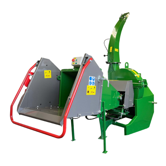
Page 9: Machine Components
MACHINE COMPONENTS Kellfri’s 13-WC15HN Chipper is designed to chip quickly and efficiently. The parts included are illustrated here and subsequently named in this operating manual. Upper chipping disc cover Infeed chute Chipping disc knife (under the chute flap) Control bar... - Page 10 STEPS TO TAKE BEFORE USE Carefully read the safety instructions and the operating instructions. Make sure that you un- derstand the safety instructions, operating instructions and warning decals. Use common sense and suitable personal protective equipment when using the product. Always check the performance of the machine combination to be used.
- Page 11 CONNECTING • Connect the machine to the tractor’s rear three-point linkage. Connect the PTO shaft. Adjust the length if required. (See instructions, p.20) • • Secure the chain properly. • Check for leaks in the hydraulic system. • Connect the 7-pin connector to the tractor. •...
- Page 12 ASSEMBLY INSTRUCTIONS Consider the following when assembling the chipper: Due to the weight of the chipper, it is recommended that two people work together to assemble it. The machine must only be lifted using the designated lifting points. Only use suitable lifting equipment with sufficient lifting capacity to lift the machine. WARNING! RISK OF CRUSHING! Do not allow anyone to stand under suspended loads! The equipment comes in a transport frame to protect it.
- Page 13 2. Install the locking device. View from the inside of the infeed table. 3. Install the control bar. 2 pcs. 1 pc (a.) (b.) Assembly on the right. Assembly on the left. Table of contents...
- Page 14 4. Fit protective guard. 4 pcs. 5. Fit stabilisers. 2 pcs. 2 pcs. Stabilisers are fitted on the right-hand and left-hand sides of the chipper. IMPORTANT! The stabilisers must be folded down and standing on the ground during operation. Table of contents...
- Page 15 6. Fit the control box, Stop – Start. 2 pcs. 2 pcs. 2 pcs. CONTROL BOX FUNCTION • 7-pin plug connected to the tractor. • Pull out the emergency stop by turning it. • Then press the green button, and a red light will come on next to the electric valve.
-
Page 16: After Use
WARNING! The cutting disc continues to rotate after the chipper is turned off so wait until the disc has come to a complete standstill before carrying out any work on the machine. AFTER USE Reduce the tractor’s speed to idling; make sure the drive shaft has stopped rotating BEFORE disconnecting the PTO. -
Page 17: Checklist Before Use
RUNNING IN THE MACHINE Although there are no restrictions regarding operating the chipper for the first time, we rec- ommend that you carry out the following checks: A. After one (1) hour of operation 1. Check that the machine is in the Safety position, see previous section. 2. -
Page 18: Connecting To The Tractor
CONNECTING TO THE TRACTOR This section describes how to connect the tractor’s 3-point linkage and the PTO shaft. It is a Category 1 3-point linkage. To achieve the longest service life and for safety reasons, the PTO shaft should be as straight as possible when the equipment is in working mode (down). Do as follows when connecting the equipment to a tractor: 1. -
Page 19: Control Levers
15. Slowly lift the machine and make sure that the length of the PTO shaft is long enough and that it is not angled too much. 16. Make sure the front and back of the machine are level with the ground, edge to edge; use the 3-point linkage to make any adjustments. - Page 20 DIRECTIONS FOR SHORTENING THE PTO SHAFT 1. Remove the protective device. 2. Cut off the transmission shaft to the desired length. NB The shaft may not be cut more than half the tube length. 3. File the edges of the tube 4.
- Page 21 CONTROL BAR FOR INFEED ROLLERS The control bar regulates the movement of the infeed rollers; forward, back and stop. 1. Mode – Infeed 2. Mode – Stop 3. Mode – Output 1. Mode – Infeed Push the reset bar towards you and then pull Control bar the control bar towards you to start the infeed rollers.
- Page 22 FLOW CONTROL FOR THE INFEED ROLLERS Use the flow control valve. The flow control can also be used to adjust the feed speed. Check the size and quality of the material to determine the correct size and the correct feed speed. Increase the speed for bushes and twigs, reduce the speed for harder timber or when there is large load in the machine.
-
Page 23: Clearing Blockages
SAFETY CHECK BEFORE MACHINE MAINTENANCE • Disconnect the PTO shaft. • Turn off the tractor engine. • Make sure all parts in the machine have come to a standstill. • Remove the ignition key from the tractor and put it in your pocket. •... - Page 24 MAINTAINING FEED ROLLERS At times, the feed rollers require servicing, for instance to remove debris, when cleaning, or to perform inspections or repairs. To safely raise and gain access to the feed rollers, there is a turnbuckle on top of the chipper. 1.
-
Page 25: Troubleshooting
TROUBLESHOOTING NOTE Make sure the machine is turned off and disconnected before performing any intervention. TROUBLESHOOTING CAUSE MEASURE Poor chip quality, wood - Blunt blades. - Check blades. unevenly chipped - Cutting distance between blades is - Adjust and grind if required. uneven or too wide. - Page 26 SETTING CHIPPING WOOD SIZE IN 13-WC17H2 Bear in mind: When the machine is shipped, the chipping disk is not adjusted for chipping but is set instead to avoid damage to the disc during transport. An “adjustment spacer” is sup- plied to adjust the chipping disc in the easiest and safest way.
- Page 27 EXTRA SPACER FOR CHIPPING WOOD SIZE 13-WC17H2 To make it possible to further adjust the chipping wood size, four extra spacers are included. We recommend that these are installed before the chipper is used. NOTE All four blades must be mounted at the same time.
- Page 28 Version 1.1 ITEM SPARE PART NO. DESIGNATION ITEM TYPE QUAN- TITY A-DIV Chipper, lower part WC17H.002 Chipper, upper part A-DIV Infeed container A-DIV Infeed hopper WC17H.003 Discharge chute (complete) R13-WC17H2.021 Stabilisers for infeed table R13-WC17H2.022 Lower stabiliser L = In stock B = Available to order T = Not available in range Table of contents...
- Page 29 Version 1.1 ITEM SPARE PART NO. DESIGNATION ITEM TYPE QUAN- TITY R13-WC17H2.013 Infeed table R13-WC17H2.014 Infeed table handle R13-WC17H2.015 Infeed table locking arm R13-WC17H2.016 Infeed table protective guard R13-WC17H2.017 Directional control valve, in- feed R13-WC17H2.018 Spring locking arm R13-WC17H2.019 Spring locking pin Table of contents...
- Page 30 Version 1.1 ITEM SPARE PART NO. DESIGNATION ITEM TYPE QUAN- TITY R13-WC15H.001.2 Hydraulic motor for infeed roller R13-WC15H.004 Control valve R13-WC17H2.009 Control box, start/stop WC17H.082 Hydraulic pump tank WC17H.095 Gearbox WC17H.084 Filter R13-WC17H2.010 Hydraulic oil tank cover WC17H.083 Hydraulic tank R23-TV100.085 Trailer connector, male, 7-pin A-DIV...
- Page 31 Version 1.1 ITEM SPARE PART NO. DESIGNATION ITEM TYPE QUAN- TITY R13-WC17H2.011 Hydraulic hose pump – solenoid valve A-DIV Solenoid valve A-DIV Hose from solenoid valve to flow valve A-DIV Inner engine oil hose A-DIV Hose from control valve to engine A-DIV Inner flow and control valve hose A-DIV...
- Page 32 Version 1.1 ITEM SPARE PART NO. DESIGNATION ITEM TYPE QUAN- TITY WC17H.049 Cutting disc R13-WC15H.011.2 Blade – double cutting R13-WC15H.023 Blade bolt, countersunk M10x45 A-DIV Bolt M16x60 R35-HRT160.025 Washer 10 MTB50.002 Locking nut M10 R60-MUTTERLÅ.021 Locking nut M12 WC17H.056 Washer 16 WC17H.057 Drive shaft for chipper disc WC17H.058...
- Page 33 Version 1.1 ITEM SPARE PART NO. DESIGNATION ITEM TYPE QUAN- TITY A-DIV Chipper, lower part WC17H.044 Cutting disc R10-UCF210 Flanged bearing housing with bearing UC210 WC17H.045 Bolt M16x35 WC17H.048 Branch crusher WC17H.093 Belt pulley 13-WC15HN.001 Speed control WC17H.095 Gearbox WC17H.082 Hydraulic pump tank WC17H.083 Hydraulic tank...
- Page 34 Version 1.1 Table of contents...
- Page 35 ITEM SPARE PART NO. DESIGNATION ITEM TYPE QUAN- TITY A-DIV Infeed hopper WC17H.030 Engine housing upper WC17H.027 Metal guard, infeed roller WC17H.041 Metal guard, infeed roller R13-WC10.002 Bearing drive shaft UCF208 100 R13-WC17H2.012 Hydraulic motor guard WC17H.037 Roller guard, lower WC17H.040 Spring for upper wing nut WC17H.033...
- Page 36 Version 1.1 Table of contents...
- Page 37 ITEM SPARE PART NO. DESIGNATION ITEM TYPE QUAN- TITY WC17H.059 Discharge chute WC17H.060 Lever and wire A-DIV Wing nut M6 A-DIV Bolt M8x140 R27-EK251.025 Flat washer M8 WC17H.064 Discharge flap WC17H.065 Spring, infeed roller WC17H.013 Locking nut M8 R27-EK251.024 M8 spring washer R27-EK251.036 Flat washer M6 WC17H.069...
-
Page 38: Grease Points
GREASE POINTS Table of contents... - Page 39 DEVIATION FORM We are grateful for your help in pointing out any defects in the product supplied to you by Kellfri. Before making a claim, read Kellfri’s general purchase terms and conditions in our catalogue or on our website www.kellfri.co.uk, and in the operating manual if supplied.
-
Page 40: Warranty Terms And Conditions
You are always welcome to give feedback or ask us about our equipment and products. Kellfri AB has a policy of continuous product development and therefore reserves the right to make modifications, e.g. to the design and appearance of the product, without prior notice.
Need help?
Do you have a question about the 13-WC17H2 and is the answer not in the manual?
Questions and answers