
Related Manuals for SIAM SUDOS-mini 2

Summary of Contents for SIAM SUDOS-mini 2
- Page 1 Tomsk Scientific Industrial Introduction Company “SIAM” LLC SUDOS – mini 2 Level gauge OPERATING MANUAL TOMSK...
-
Page 3: Table Of Contents
................... 13 ENERAL INFORMATION 5.2. A ......13 RRANGEMENT APPLICATION AND OPERATION OF COMPONENTS 5.2.1. SUDOS-mini 2 level gauge ................13 5.2.2. Ball-type Nozzle ..................16 5.2.6. Handle ......................17 5.2.7. Additional accessories ..................17 5.3. L ..................19 EVEL GAUGE OPERATION 5.3.1. - Page 4 8. MAINTENANCE ......................37 8.1. S ................... 37 CHEDULE OF MAINTENANCE 8.2. M ..................38 AINTENANCE PROCEDURE 8.2.1. Cleaning the tapered connection thread, flushing the inside of the level gauge. Cleaning the face panel and housing ................. 38 8.2.2. Maintenance of the manual valve ..............39 8.2.3.
- Page 5 Pay attention to the version of the installed software. This tool operates in combination with "DB SIAM" of а V2.5-version and above. ...
- Page 6 Maintenance of the device is to be performed only by SIAM Service Company or by certified specialists. Unauthorized opening of the device, as well as violation of operation rules, entails loss of warranty!
-
Page 7: General Product Information
The wideband Level gauge SUDOS-mini 2 (hereinafter the wideband level gauge) can be used for recording wideband echograms which are used to determine the sound speed in oil wells in a computer. - Page 8 Parameter name Norm on specifications (0 100) 3 Range of monitored pressures, kilogauss/ - monitoring resolution, kilogauss/ cm 4 Non-volatile storage capacity - for symbol reports 12064 -for graphs 2605 5 Non-volatile storage capacity * 8512 - for symbol reports -_for graphs for wideband echograms 6 Time of continuous operation under...
-
Page 9: Delivery Set
4. Automobile power unit with USB 5. Ball-type nozzle / rubber sphere 6. Device bag 7. Personal computer software: Flash drive with DB “SIAM” version 2.5 (and above). 8. Operation documentation: SUDOS-mini 2. Certificate SUDOS-mini 2. Operating manual ... -
Page 10: Safe Operation Instructions
The personnel should be trained to operate on the test-equipment. The training is performed by personnel of the manufacturing company directly or by authorized representative of SIAM Company directly on the working place. 4.3. Test object Such tests as pressure measuring and fluid level monitoring are carried... -
Page 11: Requirements To The Test Object
4.3.1. Requirements to the test object Construction and operation of a well should be performed in accordance with "Safety rules in the oil and gas industry". All Tested well, irrespective of its application and operation mode, should have a technological tap equipped with a valve and a wave metering tool seating nipple. -
Page 12: The Level Gauge Assembly Sequence
massive corrosion or damages of the nipple's thread, carrying out tests is prohibited. Clean the inner space of the nipple from paraffin, hydrates, ice and other. 4.4.2. The level gauge assembly sequence Clean the thread part of a coupling of the level gauge from sludge and check it. -
Page 13: Level Gauge Disassembly
GAI-01. The tool supports export of information to a computer. An applied software DB "SIAM" included in the delivery set, makes it possible to create and add computer data bases, to process and analyze measurement results in more detail. - Page 14 performs a level calculation, displays the operation modes and monitoring results on a digital display, as well as it registers measurement parameters and results in its fixed storage, and ensures a communication with the computer. The level gauge is powered by a built-in battery with a minimum of 1000 charge-discharge cycles.
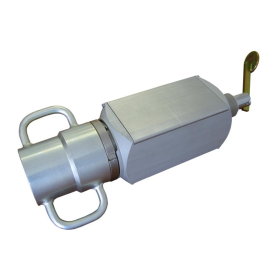
- Page 15 The level gauge consists of: – outlet valve (rotating, removable); – rotating tool body; – two install clips; – a thread jointing coupling; – a symbol display; – keyboard; 7 – an auxiliary slot to connect external devices such as a mains-operated adapter, a cable for charging from car power, a micro printer, a computer, and a visual monitoring unit;...
-
Page 16: Ball-Type Nozzle
5.2.2. Ball-type Nozzle The ball-type nozzle (the rubber sphere) is designed for generating an acoustic impulse when there is no excessive gas pressure in the annular space of the well. The ball-type nozzle is made up of the rubber sphere and the coupling. The ball- type nozzle is actuated by a violent blow of the hand on the sphere. -
Page 17: Handle
also o connect the appliance to a power supply with USB connector or to a car power supply unit with USB connector to charge the appliance battery. 5.2.6. Handle The handle ensures convenient assembly and disassembly of the level gauge on a well; and the handle is of a great length and strength that makes it possible to tighten (with an adequate moment) (see Section 4.4.2) the level... - Page 18 pulse by releasing a portion of gas into the annular space. At low overpressures and under vacuum, the valve can be used to generate an acoustic signal by letting a portion of high-pressure gas into the annulus. In this case, a set of gas-balloon equipment GBO-02 filled with nitrogen is used as a source of excess pressure.
-
Page 19: Level Gauge Operation
5.3. Level gauge operation 5.3.1. Function When monitoring the fluid level, а wave metering method is used. The operation process is rendered automatically. The participation of the operator (after mounting the device) is required only to generate an acoustic pulse using the level gauge outlet valve, or additional devices for generating acoustic pulses (ball-type nozzle, GAI-01). -
Page 20: Control And Display Units
5.3.2. Control and display units The control and display units are the following: a symbol display of operation modes, parameters and measurement results and a four-key keyboard. The display is used to show the tool's operation modes, to control the input of initial parameters (reference data) of a test, to monitor the test in progress and to display basic numerical results of the test. -
Page 21: Operation Modes Of The Tool
parameter (being changed) is displayed as a flashing sign. This means that a parameter may be entered. Navigation to the previous dimension through the measurement database. Turn on the tool. Starts a fluid level measuring process. Change any tool mode from back to the initial one by consecutive pressing the LEVEL and MODE keys (move back/ reset). - Page 22 Word records made to the set parameters are automatically recorded in a symbol report of each measurement and, then, they can be read in all records (including when transferring data to a stationary computer, etc.). In order to save time when carrying out the work directly on a well, it is recommended to set necessary parameters beforehand.
- Page 23 С К В А Ж И Н А 4 3 2 1 0 4 К У С Т 5 2 8 1 4 М Е С Т О Р . 0 0 3 Я Р К О С Т Ь И Н Д. 5 0 % 1.
- Page 24 1 — there is a table appropriate for Siberian region (Supplement 3) 2 — there is a table appropriate for Tatarstan region (Supplement 3) In addition to it, using computer and database «SIAM», it is possible to create and install to device any of four user tables (for details see Supplement 2).
- Page 25 С К О Р О С Т Ь З В У К А П О П Р А В К А When the mode 0 is chosen, the manual input of the sound speed is activated. Indicator shows the previously set sound speed (in m/s). Setting up of the required speed is to be done in the same way as in the case with setting up the number of well or well cluster.
- Page 26 В Ы П У С К Г А З А Д А Д О П . У С И Л Е Н И Е Н Е Т 1. Wideband echogram (for wideband level gauge). Mode to enable recording of wideband echograms. Wideband echograms are used to determine the speed of sound after transmission to a computer.
- Page 27 The total capacity of the storage is adequate for 12064 symbol reports and 2605 graphs. Counters return to the initial storage capacity when they are initialized or data are transferred to computer. As the entire allocated storage fills up, as each subsequent result is recorded, the first measurement is automatically 'erased' and so on.
-
Page 28: Turning The Tool On And Turning It Off
6. List of measurements. In this mode up to the three measurements for the current date and well number can be shown in the title. In the each line of measurements the time of measurement, quantity of reflections and the measured fluid level are indicated. Pressing "INPUT/OUTPUT" button —... -
Page 29: Explosion-Proofness Of The Device
Switching on Pressing one of the three keys (MODE, INPUT/OUTPUT, LEVEL) turns on the tool. After being turned on the tool remains in the same operation mode as it was in before turning off. Switching off The tool can be turned off from any operation mode by pressing consecutively the keys LEVEL and INPUT/OUTPUT. -
Page 30: Measures To Ensure And Keep The Device Explosion-Proofness During The Assembly, Disassembly And Repair Of The Device
of the device. The design of the protective component “Fib” is met with the requirements of GOST 31610.11-2014 (IEC 60079-11:2011), including leakages and clearances. Thus, the electrical circuit coming out of the battery compartment of the device is intrinsically safe. •... - Page 31 • The elements used in the protective component of “Fib” are subjected to an acceptance test: - resistors are tested for their nominal resistance; - the fuses are checked against the short-circuit current limit; • Materials used for casting the protective component “Fib” are subjected to an acceptance test according to the certificates presented.
-
Page 32: Safety And Environmental Instructions
5.3.8 Safety and environmental instructions 5.3.8.1 When operating the device, it is mandatory to comply with the requirements of the following regulatory documents: GOST 12.1.019, GOST 12.2.003, GOST 12.2.007.0, GOST IEC 60079-14-2013, GOST 31610.0 (IEC 60079-0:2011), GOST 31610.11 ( IEC 60079-11:2011), Technical Regulations of the Customs Union CU TR 012/2011 "On the safety of equipment for operation in explosive environments". - Page 33 to observe antistatic protection measures when using the device in office and technological premises, as well as during its storage. Preparation sequence for tests are is given below with references to the appropriate sections of this manual: 1. Preparation of the tool for service — see Section 6.1 2.
-
Page 34: Measuring
7. MEASURING ATTENTION! While performing work on a well, strictly follow the requirements and provisions of the Safe operating Instruction (Section 7.1. Fluid level monitoring Press the LEVEL key and keep it pressed for about one second until the l symbol appears on the display. -
Page 35: Recording A Wideband Echogram (For A Wideband Level Gauge)
In 1 or 2 sec. after the beginning of calculations, a level measurement result is displayed. E.g.: 2 6 / 0 9 С К В 6 7 8 9 4 3 1 6 : 5 1 У Р 1 0 2 7 М >... -
Page 36: Automatic Recording Of Gas Pressure In The Wellhead Annulus
will immediately switch to the echogram recording mode. Therefore, after the appearance of the inscription "RECORDING ECHOGRAM", immediately generate an acoustic impulse by briefly pressing the handle of the level gauge manual valve to the stop. 20 seconds after the beginning of the recording of the echogram, the inscription "FILTERING"... -
Page 37: Maintenance
Replacement of sealing rings Notes: 1) maintenance work is carried out by a service center of the "SIAM" company or by certified specialists of the Company. It is possible to replace the rubber ring of the exhaust valve (pos. 15 p.5) by... -
Page 38: Maintenance Procedure
8.2. Maintenance procedure ATTENTION! When using HFL follow the rules of fire prevention! Carry out the work only in well-ventilated rooms. 8.2.1. Cleaning the tapered connection thread, flushing the inside of the level gauge. Cleaning the face panel and housing Clean with diesel fuel or kerosine using a brush and a rag. -
Page 39: Maintenance Of The Manual Valve
CIATIM GOST 6267-80. After mounting the valve on the well sounder, install the latter on the Inspection bench for well sounders SKU-1 IZM 4.137.003 (SIAM Company) and purge the valve at pressure of 5…8 atm, using clean air. Test for pressure integrity with a soap solution. A slight “seepage”... -
Page 40: Flushing And Lubricating The Interface Connector
Methodology of checks is presented in the "Manual on conducting verification tests of devices and complexes manufactured by TSIIC "SIAM" LLC in operation". Tests 2 and 3 are performed at the Level gauge control test bench SKU-1 IZM 4.137.003 (SIAM company). Test 5 is carried out on the hydraulic test bench SGI-1 IZM 4.137.002 (SIAM... -
Page 41: Pressure Testing
Perform a pressure test of the tool according to Section 8.2.5. of this Instruction. If requirements of leak-proofness have been met, the tool is allowed for service, otherwise, it is not allowed for service and should be sent back to ”SIAM Company” in order to avoid trouble. -
Page 42: Storing And Transportation Of The Tool
9. STORING AND TRANSPORTATION OF THE TOOL It is necessary to store the level gauge in a special package in dry heated rooms; the ambient temperature should be in the range from -10 С up to +40 С and the air humidity content should be not more than 80%. It is permitted to transport the tool in a special package with any type of transportation when the ambient temperature is in less than —... - Page 43 2. In the well annulus there is great interference The returning acoustic signal caused by too strong vibration of the tubing has a lower amplitude than that and casing string, vibration of an electrical of the noise level. submersible pump (EPS), leaks from valves and other reasons.
-
Page 44: Supplement 2. Setting Of A User Sound Speed Correction Table
Supplement 2. Setting of a user sound speed correction table When monitoring the fluid level, an operator can select and set a user correction table according to which the tool determines an acoustic wave velocity which is either a function of a just measured annulus pressure or a function of the pressure and the level. - Page 45 С К О Р О С Т Ь З В У К А П О П Р А В К А Select the desired table number from those stored in the unit by pressing the INPUT/OUTPUT button repeatedly. Then press the MODE button to set the level gauge to any desired operating mode.
-
Page 46: Supplement 3. Dependence Of Sound Speed On Annular Pressure ( Tables For General Use )
Supplement 3. Dependence of sound speed on annular pressure (tables for general use) Table 1 - "Langepas" (averaged data for Siberia) Pressure, Sound Pressure, Sound Pressure, Sound Pressure, Sound kgf/cm 2 speed, m/s kgf/cm 2 speed, m/s kgf/cm 2 speed, m/s kgf/cm 2 speed, m/s 10,2... -
Page 47: Supplement 4. Charging The Battery
Table 2 Tatarstan" (for Tatneft fields) Pressure, Sound Pressure, Sound Pressure, Sound Pressure, Sound kgf/cm 2 speed, kgf/cm 2 speed, kgf/cm 2 speed, kgf/cm 2 speed, 10,5 11,2 11,9 12,3 13,5 14,0 15,0 17,0 20,0 26,0 34,0 48,0 60,0 81,0 Supplement 4. -
Page 48: Supplement 5. Transferring Data To A Computer
Supplement 5. Transferring data to a computer Attention! To avoid errors when transferring data to a computer, carefully read and strictly follow the requirements of the "SIAM Database v2.5" User's Manual. Perform the data transfer to a computer in the following sequence:... - Page 49 Figure 2...
- Page 50 Figure 3 Figure 4...
- Page 51 Figure 5 Figure 6...
- Page 52 Figure 7 Figure 8 Open the "Control Panel" → "System" → "Device Manager" tab.
- Page 53 Locate the newly created COM port. In the example it is USB Virtual Serial Port (COM11), see Figure 9. 3) Start "SIAM DB v2.5" database on computer. 4) In the computer database, start the import procedure. Select the number of COM port corresponding to the connected USB. In the...
- Page 54 Figure 9...
-
Page 55: Supplement 7. The Echogram Visualization In The Graphic Display
Figure 10 Supplement 7. The echogram visualization in the graphic display "INPUT/OUTPUT" button — jump to the previous graph. Pressing "BACK" and "INPUT/OUTPUT" buttons simultaneously — jump to the next graph. Pressing "MODE" button — jump to correct the left border of the graph. With each new pressing of the "INPUT/OUTPUT" button, the borderwill be changed for approximately 150 meters (depending on the velocity of sound). -
Page 56: Supplement 8. Setting The Time And Date. Initialing The Storage
echogram (in conventional units) and distance (in meters) between lines of the vertical grid. In the bottom line there will be shown: date of monitoring (day, month), time of monitoring (hour, minutes), quantity of reflections, liquid level, and annulus pressure. 0М... - Page 57 In order to save the valuable data — transfer it to the computer database before initialization of memory. The initialization process does not change the current time and date and they can be left without correction or changed partly. Attention! Initialing cannot be conducted, if the battery cell is discharged (the indicator is flashing).
-
Page 58: Supplement 9. Setting The Operator And Workshop Number And Resetting The Seconds
You can choose not to edit the time and date by pressing the "MODE" button. To repeal the time and date correction — press "MODE" button. To correct time and date — press "INPUT/OUTPUT" button. Seconds start flashing. In order to set seconds to zero — press "INPUT/OUTPUT"... -
Page 59: Supplement 10. Setting The Pressure Sensor At Zero
Supplement 10. Setting the pressure sensor at zero This mode corrects the zero drift of the pressure sensor and is intended to compensate for possible temporary zero drift and to adapt the pressure sensor to different temperature conditions. In this mode, a correction for pressure sensor zero drift is written into the level gauge storage, which is automatically taken into account for all further measurements to determine the actual pressure value. -
Page 60: Supplement 11.1. Restarting The Level Gauge
loss of information caused by mishandling of the level transmitter; a malfunction of the level transmitter itself. The inscription that appears on the display indicates the type of fault. A list of possible faults is described in Supplement 11. Supplement 11.1. - Page 61 СБОЙ FRAM - loss of previously entered information - cluster number, well number, survey type and system parameters. When the MODE button is pressed (when this fault is indicated), the system parameter area is filled with initial values. СБОЙFRAM14 - loss of user-defined tables of sound speed vs.
-
Page 62: Supplement 13. List Of Possible Malfunctions And Methods Of Rectification
FL4, НЕИСПР FL5 is deactivated. If in this case no echogram or symbol report is recorded, СБОЙ FL16 or СБОЙ FL16 will be displayed when the unit is initialised. If faults НЕИСПР FL4, НЕИСПР FL5, НЕИСПРFLES, СБОЙ FL16, СБОЙ FL17 are displayed, the device must be sent for repair. Supplement 13. - Page 63 Description of defects, external manifestations Probable cause Rectification method and additional signs 4._The level gauge does not Malfunctioning of Restarting the device by does not react to simultaneously pressing pressing the keys. The same controller program the LEVEL and MODE note is displayed for a long because buttons (Supplement...
- Page 64 REVISION RECORD SHEET Total Numbers of sheets (pages) Incoming # Ref # of sheets Signa- Revi- of supporting docu- Date (pages) of sion ture Revised Replaced Annulled ment document document...
Need help?
Do you have a question about the SUDOS-mini 2 and is the answer not in the manual?
Questions and answers