HPE 5900 Series Installation Manual
Hide thumbs
Also See for 5900 Series:
- Command reference manual (319 pages) ,
- Command reference manual (34 pages)

Related Manuals for HPE 5900 Series


Summary of Contents for HPE 5900 Series
- Page 1 HPE 5920 and 5900 Switch Series Installation Guide Part Number: P21287-001 Published: September 2019...
- Page 2 © Copyright 2016, 2019 Hewlett Packard Enterprise Development LP Notices The information contained herein is subject to change without notice. The only warranties for Hewlett Packard Enterprise products and services are set forth in the express warranty statements accompanying such products and services. Nothing herein should be construed as constituting an additional warranty.
-
Page 3: Table Of Contents
Contents Preparation for installation....................6 Product codes and descriptions......................................6 Safety recommendations........................................7 Installation site requirements......................................8 Temperature and humidity requirements..............................8 Cleanliness requirements..................................... 9 EMI requirements........................................9 Laser safety requirements....................................9 Required installation tools and accessories................................10 Installing the switch......................12 Installing the switch in a 19-inch rack..................................12 Rack requirements........................................ - Page 4 Regulatory information........................................48 Documentation feedback........................................49 Chassis views and technical specifications...............50 Chassis views............................................. 50 HPE 5920AF-24XG/HPE 5920AF-24XG TAA............................50 HPE 5900AF-48XG-4QSFP+/HPE 5900AF-48XG-4QSFP+ TAA/HPE 5900CP-48XG-4QSFP+/HPE 5900CP-48XG-4QSFP+ TAA/HPE 5900CP-48XG-4QSFP+8Gb FC B-F................51 HPE 5900AF-48XGT-4QSFP+/HPE 5900AF-48XGT-4QSFP+ TAA..................52 HPE 5900AF-48G-4XG-2QSFP+/HPE 5900AF-48G-4XG-2QSFP+ TAA................54 Technical specifications........................................55 FRUs and compatibility matrixes..................58 Power supplies............................................
- Page 5 QSFP+ port LED........................................68 Management Ethernet port LEDs................................69 10/100/1000Base-T autosensing Ethernet port LEDs........................69 1/10GBase-T autosensing Ethernet port LEDs...........................69 Cooling system........................70 HPE 5920 cooling system........................................70 HPE 5900 cooling system........................................71 Document conventions and icons..................74 Conventions..............................................74 Port numbering in examples................................... 74 Command conventions.......................................
-
Page 6: Preparation For Installation
Preparation for installation Product codes and descriptions Table 1: HPE 5920 and 5900 Switch Series models, power supplies, and fan trays Product code HPE description Alias HPE 5920 switches JG296A HPE 5920AF 24XG Switch HPE 5920AF-24XG JG555A HPE 5920AF 24XG TAA-compliant Switch... -
Page 7: Safety Recommendations
5900AF-48XGT-4QSFP+ TAA-compliant Switch, and HPE 5900AF-48G-4XG-2QSFP+ TAA-compliant Switch products are assigned Regulatory Model Numbers (RMNs). The RMNs for these products are listed in the following table. These regulatory numbers should not be confused with the marketing names HPE 5900CP and HPE 5900AF, or product codes JH036A, JH037A, and JH038. -
Page 8: Installation Site Requirements
• Before cleaning the switch, remove all power cords from the switch. Do not clean the switch with wet cloth or liquid. • Do not place the switch near water or in a damp environment. Prevent water or moisture from entering the switch chassis. •... -
Page 9: Cleanliness Requirements
Cleanliness requirements Dust buildup on the chassis might result in electrostatic adsorption, which causes poor contact of metal components and contact points, especially when indoor relative humidity is low. In the worst case, electrostatic adsorption can cause communication failure. The dust concentration limit s listed in Dust concentration limit in the equipment room. Table 2: Dust concentration limit in the equipment room Substance Concentration limit (particles/m... -
Page 10: Required Installation Tools And Accessories
Product code Description Quantity Applicable models 5066-0850 1 U mounting bracket kit (including one pair 1 kit All HPE 5920&5900 switches of mounting brackets and eight M4 countersunk screws) 5185-8681 1 U short slide rail kit (including one pair of 1 kit All HPE 5920&5900 switches... - Page 11 Product code Description Quantity Applicable models 5185-8748 Removable cable tie All power supplies 5185-8627 Console cable All HPE 5920&5900 switches 5185-8722 SFP/SFP+ dust plug Optional • HPE 5920AF-24XG • HPE 5920AF-24XG TAA • HPE 5900AF-48XG-4QSFP+ • HPE 5900AF-48XG-4QSFP+ TAA •...
-
Page 12: Installing The Switch
Installing the switch CAUTION: Keep the tamper-proof seal on a mounting screw on the chassis cover intact, and if you want to open the chassis, contact Hewlett Packard Enterprise for permission. Otherwise, Hewlett Packard Enterprise shall not be liable for any consequence caused thereby. -
Page 13: Rack Requirements
HPE 5920AF-24XG Using mounting brackets and short slide • rails (provided). (39.37 in). • HPE 5920AF-24XG TAA • Distance between the front and rear rack posts—401 mm (15.79 in) to 895 mm (35.24 in). Depth—A minimum of 1000 mm •... -
Page 14: Rack-Mounting Procedures At A Glance
Figure 3: Rack mounting rail kit (short slide rails) (1) Chassis rail (2) Short slide rail Figure 4: Rack mounting rail kit (long slide rails) (1) Chassis rail (2) Long slide rail Rack-mounting procedures at a glance Figure 5: Rack-mounting procedure IMPORTANT: To make sure that the switch is securely installed in the rack, you must install both the mounting brackets and rack-mounting rail kit. -
Page 15: Attaching The Mounting Brackets, Chassis Rails, And Grounding Cable To The Chassis
Grounding point Remarks • HPE 5920AF-24XG One primary grounding point (with a grounding sign) and one auxiliary • HPE 5920AF-24XG TAA grounding point. • HPE 5900AF-48XG-4QSFP+ One primary grounding point (with a • As a best practice, connect the grounding sign) and two auxiliary grounding cable to the primary •... - Page 16 Figure 6: Mounting and grounding positions of the HPE 5920AF-24XG/5920AF-24XG TAA switches (1) Rear mounting position (2) Primary grounding point (3) Auxiliary grounding point 1 (4) Front mounting position Figure 7: Mounting and grounding positions of the HPE 5900AF-48XG-4QSFP+/5900AF-48XG-4QSFP+ TAA/...
-
Page 17: Attaching The Mounting Brackets And Chassis Rails To The Chassis
Figure 8: Mounting and grounding positions of the HPE 5900AF-48G-4XG-2QSFP+/5900AF-48G-4XG-2QSFP+ TAA switches (1) Auxiliary grounding point 2 (2) Rear mounting position (3) Primary grounding point (4) Auxiliary grounding point 1 (5) Front mounting position Attaching the mounting brackets and chassis rails to the chassis Procedure 1. - Page 18 Figure 9: Attaching the rear mounting brackets/chassis rails/grounding cable to the chassis Figure 10: Attaching the front mounting brackets/chassis rails to the chassis 2. Use M4 screws (provided) to attach the mounting brackets to the chassis. 3. Align the chassis rails with the rail mounting holes in the chassis: Installing the switch...
-
Page 19: Connecting The Grounding Cable
a. If the mounting brackets are in the rear mounting position, align the chassis rails with the screw holes at the front of the side panels. See Figure Attaching the rear mounting brackets/chassis rails/grounding cable to the chassis. b. If the mounting brackets are in the front mounting position, align the chassis rails with the screw holes at the rear of the side panels. -
Page 20: Mounting The Switch In The Rack
Figure 11: Installing the side rails Mounting the switch in the rack This task requires two people. Procedure 1. Wear an ESD wriststrap and make sure it makes good skin contact and is reliably grounded. 2. Verify that the mounting brackets and chassis rails have been securely attached to the switch chassis. 3. - Page 21 Figure 12: Mounting the switch in the rack (1) 6. Use screws (user-supplied) to attach the mounting brackets to the rack, as shown in the following figure. To secure the switch in the rack, make sure the front ends of the slide rails reach out of the chassis rails. Installing the switch...
-
Page 22: Grounding The Switch
Figure 13: Mounting the switch in the rack (2) Grounding the switch WARNING: Correctly connecting the switch grounding cable is crucial to lightning protection and EMI protection. The power input end of the switch has a noise filter, whose central ground is directly connected to the chassis to form the chassis ground (commonly known as PGND). -
Page 23: Grounding The Switch By Using The Ac Power Cord
If a grounding strip is available at the installation site, connect the grounding cable to the grounding strip. Procedure 1. Attach the two-hole grounding lug at one end of the grounding cable to a grounding point on the switch chassis. (See Connecting the grounding cable on page 19.) 2. - Page 24 Figure 15: Grounding through the PE wire of the AC power cord (1) Three-wire AC power cable (2) Chassis rear panel NOTE: To guarantee the grounding effect, use the grounding cable provided with the switch to connect to the grounding strip in the equipment room as long as possible.
-
Page 25: Installing/Removing A Fan Tray
See callout 1 in Figure 16: Installing a fan tray in the HPE 5900AF-48XG-4QSFP+ on page 26 or Figure 17: Installing a fan tray in the HPE 5920AF-24XG on page 26. -
Page 26: Removing A Fan Tray
4. Fasten the captive screw on the fan tray with a Phillips screwdriver until the fan tray is securely attached in the chassis. See callout 2 in Figure 16: Installing a fan tray in the HPE 5900AF-48XG-4QSFP+ on page 26 or Figure 17: Installing a fan tray in the HPE 5920AF-24XG on page 26. -
Page 27: Installing/Removing A Power Supply
Procedure 1. Wear an ESD wriststrap and make sure it makes good skin contact and is reliably grounded. 2. Loosen the captive screw of the fan tray with a Phillips screwdriver until it is fully disengaged from the switch chassis. 3. -
Page 28: Installing A Power Supply
Installing a power supply CAUTION: • Follow the forward inertia of the power supply when inserting it into the chassis, and make sure that the power supply has firm contact with the connectors on the backplane. • To prevent damage to the connectors inside the switch chassis, insert the power supply gently. If you encounter a hard resistance while inserting the power supply, pull out the power supply and insert it again. -
Page 29: Removing A Power Supply
Figure 21: Installing a filter module Removing a power supply CAUTION: • If the switch has two power supplies, removing one power supply does not affect the operation of the switch. If the switch has only one power supply, removing the power supply powers off the switch. The power cord color code scheme in Figure 22: Removing the DC power cord on page 30 is for illustration only. - Page 30 Figure 22: Removing the DC power cord (1) Press the tabs on the power cord connector with your (2) Pull the power cord connector out thumb and forefinger Figure 23: Removing the power supply (1) Pivot the latch to the right with your thumb (2) Pull the power supply out Installing the switch...
-
Page 31: Connecting The Power Cord
Connecting the power cord CAUTION: • Provide a circuit breaker for each power supply. • Before you connect the power cord for a power supply, make sure that the circuit breaker for the power supply is turned off. Procedure Connecting the 650W AC power supply on page 31 •... -
Page 32: Connecting The 650W Dc Power Supply
Connecting the 650W DC power supply CAUTION: The power cord color code scheme in Figure 25: Connecting the 650W DC power supply on page 32 is for illustration only. The cable delivered for your country/region might use a different color scheme. When you connect the power cord, always identify the polarity symbol on its wires. -
Page 33: Accessing The Switch For The First Time
Accessing the switch for the first time Procedure 1. Setting up the configuration environment on page 33 2. Connecting the console cable on page 33 3. Setting terminal parameters on page 34 4. Powering on the switch on page 35 Setting up the configuration environment Procedure The first time you access the switch you must use a console cable to connect a configuration terminal, for example, a PC, to the... -
Page 34: Setting Terminal Parameters
Figure 27: Console cable RJ-45 Signal DB-9 Signal To connect a terminal (for example, a PC) to the switch: Procedure 1. Plug the DB-9 female connector of the console cable to the serial port of the PC. 2. Connect the RJ-45 connector to the console port of the switch. NOTE: •... -
Page 35: Powering On The Switch
2. After the startup completes, use the CLI to configure the switch. For more information about the configuration commands and CLI, see HPE 5920 & 5900 Switch Series Configuration Guide and HPE 5920 & 5900 Switch Series Command References. -
Page 36: Setting Up An Irf Fabric
Setting up an IRF fabric You can use HPE IRF technology to connect and virtualize the switches into a large virtual switch called an "IRF fabric" for flattened network topology, and high availability, scalability, and manageability. To set up IRF links between the switches, use SFP+ ports, 1/10-GE Ethernet ports, or QSFP+ ports. -
Page 37: Planning Irf Fabric Size And The Installation Site
Distribute the IRF member switches in different racks to implement the top-of-rack (ToR) access solution for a data center. NOTE: As your business grows, you can plug an HPE 5920 or 5900 switch into an IRF fabric to increase the switching capacity without any topology change or replacement. - Page 38 Figure 29: IRF fabric in daisy chain topology Figure 30: IRF fabric in ring topology Setting up an IRF fabric...
-
Page 39: Identifying Physical Irf Ports On The Member Switches
52 form one group. • On the HPE 5900AF-48XGT-4QSFP+ and 5900AF-48XGT-4QSFP+ TAA switches, the 1/10-GE ports are grouped by port number in ascending order, starting from one. Every four 1/10-GE ports form one group. A common practice is to use one 1/10-GE port or SFP+ port group for IRF connections, and bind every two 1/10-GE port or SFP+ ports in the group to an IRF port for increased bandwidth and availability. -
Page 40: Planning The Cabling Scheme
On the HPE 5900AF-48G-4XG-2QSFP+ and 5900AF-48G-4XG-2QSFP+ TAA switches, SFP+ ports numbered 49, 50, 51, and 52 form one group. • On the HPE 5900AF-48XGT-4QSFP+ and 5900AF-48XGT-4QSFP+ TAA switches, the 1/10-GE ports are grouped by port number in ascending order, starting from one. Every four 1/10-GE ports form one group. -
Page 41: Connecting The Irf Member Switches In One Rack
Remarks • HPE 5920AF-24XG • SFP+/QSFP+ network cables If the IRF member switches are far away from one another, choose the • HPE 5920AF-24XG TAA • •\SFP+/QSFP+ transceiver modules SFP+/QSFP+ transceiver modules with and fibers optical fibers. • HPE 5900AF-48XG-4QSFP+ If the IRF member switches are all in •... -
Page 42: Connecting The Irf Member Switches In A Tor Solution
• Execute the display irf configuration command to verify the basic IRF settings. More information HPE 5920 & 5900 Switch Series Fundamentals Configuration Guide HPE 5920 & 5900 Switch Series IRF Configuration Guide Connecting the physical IRF ports NOTE: Wear an ESD wrist strap when you connect SFP+ network cables or SFP+ transceiver modules and fibers. For how to connect them, see SFP/SFP+/XFP Transceiver Modules Installation Guide and QSFP+ Transceiver Modules/Cables Installation Guide. -
Page 43: Accessing The Irf Fabric To Verify The Configuration
2. Create a Layer 3 interface, assign it an IP address, and make sure the IRF fabric and the remote network management station can reach each other. 3. Use Telnet, web, or SNMP to access the IRF fabric from the network management station. (See HPE 5920 & 5900 Switch Series Fundamentals Configuration Guide.) 4. -
Page 44: Maintenance And Troubleshooting
NOTE: You can use the LEDs on the power supply to identify a power supply failure. For more information about the LEDs on a power supply, see HPE A58x0AF 650W AC (JC680A) & 650W DC (JC681A) Power Supplies User Guide or HPE FlexFabric Switch 650W 48V Hot Plug NEBS Compliant DC Power Supply (JH336A) User Guide. -
Page 45: No Display On The Configuration Terminal
No display on the configuration terminal Symptom The configuration terminal has no display when the switch is powered on Action 1. Verify that the power system is operating correctly. 2. Verify that the switch is operating correctly. 3. Verify that the console cable has been connected correctly. 4. -
Page 46: Websites
Websites General websites Hewlett Packard Enterprise Information Library www.hpe.com/info/EIL Single Point of Connectivity Knowledge (SPOCK) Storage compatibility matrix www.hpe.com/storage/spock Storage white papers and analyst reports www.hpe.com/storage/whitepapers For additional websites, see Support and other resources. Websites... -
Page 47: Support And Other Resources
Packard Enterprise Support Center More Information on Access to Support Materials page: www.hpe.com/support/AccessToSupportMaterials IMPORTANT: Access to some updates might require product entitlement when accessed through the Hewlett Packard Enterprise Support Center. You must have an HPE Passport set up with relevant entitlements. Support and other resources... -
Page 48: Customer Self Repair
Remote support and Proactive Care information HPE Get Connected www.hpe.com/services/getconnected HPE Proactive Care services www.hpe.com/services/proactivecare HPE Proactive Care service: Supported products list www.hpe.com/services/proactivecaresupportedproducts HPE Proactive Care advanced service: Supported products list www.hpe.com/services/proactivecareadvancedsupportedproducts Proactive Care customer information Proactive Care central www.hpe.com/services/proactivecarecentral Proactive Care service activation www.hpe.com/services/proactivecarecentralgetstarted... -
Page 49: Documentation Feedback
Hewlett Packard Enterprise is committed to providing documentation that meets your needs. To help us improve the documentation, send any errors, suggestions, or comments to Documentation Feedback (docsfeedback@hpe.com). When submitting your feedback, include the document title, part number, edition, and publication date located on the front cover of the document. -
Page 50: Chassis Views And Technical Specifications
27. The HPE 5920AF-24XG and 5920AF-24XG TAA switches also come with the fan tray slots empty. You must install two fan trays for the HPE 5920AF-24XG and 5920AF-24XG TAA for adequate heat dissipation, and their models must be the same. In this figure, two LSVM1FANSC fan trays are installed. -
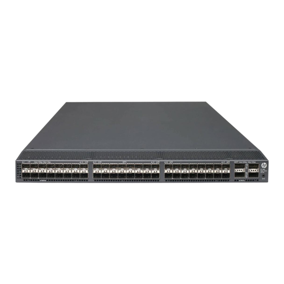
Page 51: Hpe 5900Af-48Xg-4Qsfp+/Hpe 5900Af-48Xg-4Qsfp+ Taa/Hpe 5900Cp-48Xg-4Qsfp+/Hpe 5900Cp-48Xg-4Qsfp+ Taa/Hpe 5900Cp-48Xg-4Qsfp+8Gb Fc B-F
Figure 36: Left side panel (1) Primary grounding point (2) Auxiliary grounding point 1 HPE 5900AF-48XG-4QSFP+/HPE 5900AF-48XG-4QSFP+ TAA/HPE 5900CP-48XG-4QSFP +/HPE 5900CP-48XG-4QSFP+ TAA/HPE 5900CP-48XG-4QSFP+8Gb FC B-F Figure 37: Front panel (1) SFP+ port (2) SFP+ port LED (3) QSFP+ port (4) QSFP+ port LED... -
Page 52: Hpe 5900Af-48Xgt-4Qsfp+/Hpe 5900Af-48Xgt-4Qsfp+ Taa
For more information about installing and removing the power supply, see Installing/removing a power supply on page 27. The HPE 5900AF-48XG-4QSFP+, 5900AF-48XG-4QSFP+ TAA, FlexFabric 5900CP 48XG 4QSFP+, 5900CP-48XG-4QSFP+ TAA, and 5900CP-48XG-4QSFP+8Gb FC B-F switches also come with the fan tray slots empty. You must install two fan trays for the HPE 5900AF-48XG-4QSFP+, 5900AF-48XG-4QSFP+ TAA, 5900CP-48XG-4QSFP+, 5900CP-48XG-4QSFP+ TAA, and 5900CP-48XG-4QSFP+8Gb FC B-F for adequate heat dissipation, and their models must be the same. - Page 53 650W AC power supplies are installed. For more information about installing and removing the power supply, see Installing/removing a power supply on page 27. The HPE 5900AF-48XGT-4QSFP+ and 5900AF-48XGT-4QSFP+ TAA switches also come with the fan tray slots empty. You must install two fan trays for the HPE 5900AF-48XGT-4QSFP+ and 5900AF-48XGT-4QSFP+ TAA switches for adequate heat dissipation, and their models must be the same.
-
Page 54: Hpe 5900Af-48G-4Xg-2Qsfp+/Hpe 5900Af-48G-4Xg-2Qsfp+ Taa
650W AC power supplies are installed. For more information about installing and removing the power supply, see Installing/removing a power supply on page 27. The HPE 5900AF-48G-4XG-2QSFP+ and 5900AF-48G-4XG-2QSFP+ TAA switches also come with the fan tray slots empty. You must install two fan trays for the HPE 5900AF-48G-4XG-2QSFP+ and 5900AF-48G-4XG-2QSFP+ TAA switches for adequate heat dissipation, and their models must be the same. -
Page 55: Technical Specifications
Figure 45: Left side panel (1) Primary grounding point (2) Auxiliary grounding point 1 Technical specifications HPE 5900AF-48XG-4 QSFP+/HPE 5900AF-48XG-4 QSFP + TAA/HPE HPE 5900AF-48G-4X 5900AF-48XGT-4 5900CP-48XG-4 QSFP G-2QSFP+/HPE Item 5920AF-24XG/HPE QSFP+/HPE +/HPE 5900AF-48G-4X 5920AF-24XG TAA 5900AF-48XGT-4 5900CP-48XG-4 QSFP G-2QSFP+ TAA... - Page 56 HPE 5900AF-48XG-4 QSFP+/HPE 5900AF-48XG-4 QSFP + TAA/HPE HPE 5900AF-48G-4X 5900AF-48XGT-4 5900CP-48XG-4 QSFP G-2QSFP+/HPE Item 5920AF-24XG/HPE QSFP+/HPE +/HPE 5900AF-48G-4X 5920AF-24XG TAA 5900AF-48XGT-4 5900CP-48XG-4 QSFP G-2QSFP+ TAA QSFP+ TAA + TAA/HPE 5900CP-48XG-4 QSFP +8Gb FC B-F AC-input voltage • Rated voltage: 100 •...
- Page 57 HPE 5900AF-48XG-4 QSFP+/HPE 5900AF-48XG-4 QSFP + TAA/HPE HPE 5900AF-48G-4X 5900AF-48XGT-4 5900CP-48XG-4 QSFP G-2QSFP+/HPE Item 5920AF-24XG/HPE QSFP+/HPE +/HPE 5900AF-48G-4X 5920AF-24XG TAA 5900AF-48XGT-4 5900CP-48XG-4 QSFP G-2QSFP+ TAA QSFP+ TAA + TAA/HPE 5900CP-48XG-4 QSFP +8Gb FC B-F Melting current of • 10 A @ 250 VAC •...
-
Page 58: Frus And Compatibility Matrixes
FRUs and compatibility matrixes This appendix describes the field replaceable units (FRUs) available for the HPE 5920 and 5900 Switch Series and their compatibility. All the FRUs in this appendix are hot swappable. Power supplies Power Specifications Switch model Reference supply •... - Page 59 Maximum power consumption 60 W Documentation reference HPE LSWM1HFANSC & LSWM1HFANSCB Installation Manual LSVM1FANSC ( for the HPE 5920AF-24XG and 5920AF-24XG TAA switches) Fans Three 40 × 40 × 28 mm (1.57 × 1.57 × 1.1 in) fans Fan speed...
- Page 60 Maximum power consumption 22.7 W Documentation reference HPE LSVM1FANSC & LSVM1FANSCB Fan Assemblies Installation Manual LSVM1FANSCB ( for the HPE 5920AF-24XG and 5920AF-24XG TAA switches) Fans Three 40 × 40 × 28 mm (1.57 × 1.57 × 1.1 in) fans Fan speed...
-
Page 61: Ports And Leds
USB port Every HPE 5900 switch has one OHC-compliant USB2.0 port that can upload and download data at a rate up to 12 Mbps. You can use this USB port to access the file system on the Flash of the switch, for example, to upload or download application and configuration files. - Page 62 HPE description wavelengt Connector bandwidth transmission code (μm) h (nm) (MHz x km) distance HPE X120 1G SFP RJ45 Category-5 twisted 100 m (328.08 JD089B RJ-45 T Transceiver pair 550 m (1804.46 Multi-mode, 50/125 500 m (1640.42 HPE X120 1G SFP LC...
- Page 63 Table 10: SFP+ network cables available for the SFP+ ports Product code HPE description Max transmission distance JD095C HPE X240 10G SFP+ SFP+ 0.65m DA Cable 0.65 m (2.13 ft) JD096C HPE X240 10G SFP+ SFP+ 1.2m DA Cable 1.2 m (3.94 ft)
-
Page 64: Qsfp+ Port
As a best practice, use HPE 1000 Mbps SFP transceiver modules, SFP+ transceiver modules, or SFP+ network cables for the SFP+ ports on the switch. The HPE SFP and SFP+ transceiver modules and SFP+ network cables are subject to change over time. - Page 65 • 1311 Transceiver Module • 1331 Table 12: 40G QSFP+ network cables available for the HPE 5900 switches Product code HPE description Max transmission distance JG326A HPE X240 40G QSFP+ QSFP+ 1m Direct Attach Copper Cable 1 m (3.28 ft)
-
Page 66: 10/100/1000Base-T Autosensing Ethernet Port
• As a best practice, use QSFP+ transceiver modules or QSFP+ network cables for the QSFP+ ports on the switch. The HPE QSFP+ transceiver modules and QSFP+ network cables are subject to change over time. For the most up-to-date list of HPE QSFP+ transceiver modules and QSFP+ network cables, contact your Hewlett Packard Enterprise sales representative or technical support engineer. -
Page 67: 1/10Gbase-T Autosensing Ethernet Port
IEEE 802.3i • IEEE 802.3u Compatible standards • IEEE 802.3ab 1/10GBase-T autosensing Ethernet port The HPE 5900AF-48XGT-4QSFP+ and HPE 5900AF-48XGT-4QSFP+ TAA switches have 1/10GBase-T autosensing Ethernet ports. Table 14: 1/10GBase-T autosensing Ethernet port specifications Item Specification Connector type RJ-45 Port transmission rate 1/10 Gbps, full duplex, MDI/MDI-X autosensing •... -
Page 68: Sfp+ Port Led
Table 15: System status LED description LED Mark Status Description Steady green The switch is operating correctly. Flashing green The switch is performing power-on self test (POST). The system has failed to pass POST or has problems such as fan Steady red failure. -
Page 69: Management Ethernet Port Leds
Management Ethernet port LEDs A management Ethernet port has one LINK LED and one ACT LED to show its link and data transmission status. Table 18: Management Ethernet port LEDs description LED mark Status Description LINK The management Ethernet port is not connected. Steady green The management Ethernet port is operating at 10/100/1000 Mbps. -
Page 70: Cooling System
HPE 5920 cooling system The fan trays in the HPE 5920AF-24XG and 5920AF-24XG TAA switches must be the same type: LSVM1FANSC or LSVM1FANSCB. •... -
Page 71: Hpe 5900 Cooling System
IMPORTANT: The chassis and the power supplies use separate air aisles. Make sure both aisles are not blocked. HPE 5900 cooling system Table 21: Compatibility matrix between the HPE 5900 switch models and fan trays on page 71 describes fan trays available for the HPE 5900 switches. - Page 72 Figure 52: Airflow through the HPE 5900AF-48XG-4QSFP+ chassis (with LSWM1FANSCB fan trays) on page 72.
- Page 73 (1)Power supply air vents (2) Fan tray air vents (3) Network port-side air vents IMPORTANT: The chassis and the power supplies use separate air aisles. Make sure both aisles are not blocked. Cooling system...
-
Page 74: Document Conventions And Icons
Document conventions and icons Conventions This section describes the conventions used in the documentation. Port numbering in examples The port numbers in this document are for illustration only and might be unavailable on your device. Command conventions Convention Description Boldface Bold text represents commands and keywords that you enter literally as shown. -
Page 75: Symbols
Symbols Convention Description An alert that calls attention to important information that if not understood or followed can result in WARNING! personal injury. An alert that calls attention to important information that if not understood or followed can result in CAUTION: data loss, data corruption, or damage to hardware or software.
Need help?
Do you have a question about the 5900 Series and is the answer not in the manual?
Questions and answers