Table of Contents
Advertisement
Quick Links
XX200-01-01
V1544 MATRIX SWITCHING
AND CONTROL SYSTEM
Vicon Industries Inc. does not warrant that the functions contained in this equipment will meet your
requirements or that the operation will be entirely error free or perform precisely as described in the
documentation. This system has not been designed to be used in life-critical situations and must not
be used for this purpose.
Copyright © 2010 Vicon Industries Inc. All rights reserved.
Product specifications subject to change without notice.
VICON INDUSTRIES INC., 89 ARKAY DRIVE, HAUPPAUGE, NEW YORK 11788
TEL: 631-952-CCTV (2288) FAX: 631-951-CCTV (2288) TOLL FREE: 800-645-9116
24-Hour Technical Support: 800-34-VICON (800-348-4266)
UK: 44/(0) 1489-566300 WEB: www.vicon-cctv.com
Vicon Part No. 8009-8200-01-01
Rev 0910
Advertisement
Table of Contents

Subscribe to Our Youtube Channel
Related Manuals for Vicon PILOT PLUS V1544

Summary of Contents for Vicon PILOT PLUS V1544
- Page 1 V1544 MATRIX SWITCHING AND CONTROL SYSTEM Vicon Industries Inc. does not warrant that the functions contained in this equipment will meet your requirements or that the operation will be entirely error free or perform precisely as described in the documentation. This system has not been designed to be used in life-critical situations and must not be used for this purpose.
- Page 3 The product shows a significant change in performance. 2. Retain Instructions - Retain all safety and operating 18. Replacement Parts - Use only Vicon specified replacement instructions for future reference. parts or an approved equivalent to prevent unit damage and 3.
- Page 4 Important Safeguards – Indoor Use (Cont) 22. For Rack-Mounted Units Only – The following precautions apply to all rack-mounted units. Elevated Operating Ambient - If installed in a closed or multi- unit rack assembly, the operating ambient temperature of the rack environment may be greater than room ambient.
- Page 5 FCC Notice Note: Complies with Federal Communications Commission Rules & Regulations Part 15, Subpart B for a Class A digital device. WARNING This equipment generates and uses radio frequency energy and if not installed and used properly, that is, in strict accordance with the manufacturer’s instruction, may cause interference to radio and television reception.
-
Page 6: Table Of Contents
Table of Contents Chapter 1 Introduction ........................1-1 General Information ........................1-2 System Capabilities ......................1-3 Organization of this Manual ....................... 1-5 Glossary ............................. 1-6 Chapter 2 Installation and Operation.................... 2-1 Installation ..........................2-2 Unpacking .......................... - Page 7 Table of Contents Joystick ........................2-18 Other Controls and Connectors ................... 2-18 Powering the Unit On ......................2-18 Navigating the User Interface ..................... 2-19 Linux Operating System Functions ................2-20 Accessing the Operating System Online Help ............. 2-20 Operating System Root Password ................
- Page 8 Table of Contents Camera Partitions ......................3-20 Monitors ..........................3-20 TDT Position ........................ 3-23 Alarms ..........................3-29 Common Stack Mode Example ................... 3-31 Independent Stack Mode Example ................3-33 First Available Alarm Mode Example ................3-35 Alarm Action ........................
- Page 9 Table of Contents Chapter 4 Maintenance ........................4-1 Introduction ..........................4-2 Fuse Replacement ........................4-3 Crosspoint Reset........................4-4 Using the V1332AF-1 Relay/Audio-Follow-Video Switcher ............4-5 Adding or Replacing Circuit Cards ..................... 4-6 Host Computer Connector ......................4-8 Storage ............................
- Page 10 Table of Contents Trademarks Vicon, its logo, Vicoax and Pilot Plus are registered trademarks or trademarks of Vicon Industries Inc. Linux is a registered trademark of Linus Torvalds. Gnome is a trade mark of The GNOME Project. Slo-Blo is a registered trademark of Littelfuse.
- Page 11 viii Table of Contents...
- Page 12 General Information Chapter 1 Introduction This chapter provides general information about the Pilot Plus. The chapter consists of the following topics: Topic Page General Information Organization of this Manual Glossary Pilot Plus XX200-00...
-
Page 13: Chapter 1 Introduction
Chapter 1 Introduction General Information The Pilot Plus™ V1544 Matrix Switching and Control System is the ideal system to control CCTV systems of up to 128 cameras by 8 monitors. The system is scalable in 32 camera increments. The base unit has a built-in switcher board capable of supporting 32 cameras and 8 monitors. -
Page 14: System Capabilities
General Information The Configurator provides an intuitive graphical user interface that enables you to set up system parameters, such as: Timed or Triggered Event Programming Keypad Setup Receiver Profile Configuration Camera Setup Titling and Identification of Cameras, Monitors and Presets Monitor Setup Salvo and Tour Configuration Alarm Processing Configuration... - Page 15 Chapter 1 Introduction 8 monitors 128 Receivers for PTZ control 8 Keypads (including the Pilot Plus front panel keypad) 32 local alarm inputs; 128 receive and host port alarms Descriptive titling and time and date for cameras or locations Alarm prioritizing 32 Tours Up to 99 Presets for PTZ cameras 24 Salvos...
-
Page 16: Organization Of This Manual
Organization of this Manual Organization of this Manual Chapter Description Introduction: Provides general information about the system. Installation and Operation: Describes how to install the Pilot Plus and operation instructions, including a description of navigating the Linux® operating system Configuration: Describes how to create a custom profile for your system. -
Page 17: Glossary
Chapter 1 Introduction Glossary Term Description Alarm Interface A device that senses a change in status from an alarm input and communicates that information to the Pilot Plus. FIFO First In, First Out. Applicable to alarms and how they are handled by the system. Keypad Input device used to control cameras, monitors and other system actions. - Page 18 Installation Chapter 2 Installation and Operation This chapter provides installation and operation information for the Pilot Plus. The chapter consists of the following topics: Topic Page Installation Operation 2-15 Pilot Plus XX200-00...
-
Page 19: Chapter 2 Installation And Operation
Carefully open the carton. Remove the Accessory Kit and the unit from the box and place them on a large, flat working surface. Open the Accessory Kit and verify the hardware contained in the kit against the following table. Vicon Part Number Description (Qty) Purpose... -
Page 20: Installing The Unit
Installation Vicon Part Number Description (Qty) Purpose F004802505 3-Position Male Used to connect wiring to the Alarm Relay Connector (1) terminal block. F004802508 6-Position Terminal Used to connect wiring to Keypad and Receiver Block Plug (2) terminal blocks. S56G0000004 16-Pin Terminal Block Used to connect wiring to Alarm 1-16 and Alarm 17-32 terminal blocks. -
Page 21: Attaching The Mounting Ears And Handles
Chapter 2 Installation and Operation unit. To install the tilt stand and bumper feet, select the following from the Accessory Kit: Tilt Stand and Feet Kit 1291304205 Bumper Feet 8000811801 1. Locate the screw holes on the underside of the unit. 2. -
Page 22: Connections And Wiring
Installation Connections and Wiring This section describes connecting the cameras, monitors, receivers, alarms, keypads, audio switcher and alarm relay outputs to the unit. The figure below shows the V1544 back panel. The back panel connectors and controls are described in the table that follows. Connector or Control Description Power Cord... - Page 23 Alarm Relay Outputs 3-pin terminal block connector used to connect external relays for control purposes. Keypad Inputs 6-pin terminal block used to connect Vicon V1300X series, V1411 or a host CPU to the system. Receiver Outputs 6-pin terminal block used to connect receivers or dome controls to the system for PTZ control.
-
Page 24: Camera Connection
Unused BNC connectors must be terminated with a 75 ohm terminator. Cameras may be looped to other devices, such as a DVR, using the V15RCB-24 cable (optional, available from Vicon). Each looping BNC connector is labeled from A to H. The camera input numbers correspond to the BNC letters as shown in the table that follows. -
Page 25: Monitor Connection
The Pilot Plus is compatible with the Vicon V1300X series, the V1411X series and and the V1400X-DVC keypads. You can also connect the keypads to the Vicon V1400X-IDL series Intelligent Distribution Line Control (IDL) and connect the IDL to the Pilot Plus. -
Page 26: Receiver Connection
The Pilot Plus is compatible with the Vicon V12xx; V13xx; Dome; Vicoax®; and Simplex receivers. You can also connect the receivers to the Vicon V1400X-IDL series Intelligent Distribution Line Control and connect the IDL to the Pilot Plus. - Page 27 2-10 Chapter 2 Installation and Operation 3. Using wire strippers, remove approximately 0.25 in. (0.64 cm) from the two wires. 4. Note the position of pin 1 on the terminal block. 5. Connect the wires from the receivers or IDL in accordance with the pinout data that follows.
-
Page 28: Alarm Inputs
2-11 Installation Alarm Inputs Note: Refer to the Cable Recommendations section in the Maintenance chapter for information on the type of cables to be used for twisted-pair connection. Alarm Inputs are wired directly into the Pilot Plus. There are two 16-position terminal blocks labeled ALARM 1-16 and ALARM 17-32 on the rear panel. - Page 29 2-12 Chapter 2 Installation and Operation Pin # Name Pin # Name ALARM 4 ALARM 12 ALARM 5 ALARM 13 ALARM 6 ALARM 14 ALARM 7 ALARM 15 ALARM 8 ALARM 16 ALARM 17-31 Terminal Block Plug Pin # Name Pin # Name ALARM 17...
-
Page 30: Alarm Relay Output
2-13 Installation 6. Connect the terminal block plug into the respective alarm terminal block. Alarm Relay Output Note: Refer to the Cable Recommendations section in the Maintenance chapter for information on the type of cables to be used for twisted-pair connection. -
Page 31: Relay/Audio Switcher (Audioswitch)
Chapter 2 Installation and Operation Relay/Audio Switcher (AUDIOSWITCH) The Pilot Plus may be connected to Vicon’s Relay/Audio-Follow-Video Switchers. Use of a relay/audio switcher allows audio and video signals to be switched simultaneously, via the Pilot Plus's internal video switching system. -
Page 32: Operation
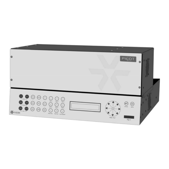
2-15 Operation Operation The following paragraphs describe the front panel controls, how to boot up the unit and shut it down. There is also a brief description of the operating system and how to access basic system functions and utilities. Front Panel The Pilot Plus has a touch-sensitive front panel. -
Page 33: Function Keys
2-16 Chapter 2 Installation and Operation Function Keys Description TOUR To start a tour, enter a tour number on the numeric keypad and press TOUR to initiate the respective tour. For example, pressing 1 and then TOUR will start Tour You can also use the TOUR key to advance to the next step of the tour, bypassing the dwell time. - Page 34 2-17 Operation Description Press MON followed by a number on the numeric keypad and then MON again to select a monitor in the system. For example, press MON > 2 > MON to select monitor Enter a camera number on the numeric keypad and press CAM again to select a camera in the system.
-
Page 35: Lcd Display
2-18 Chapter 2 Installation and Operation LCD Display The LCD display provides information about the system cameras, monitors and presets. When MENU is pressed, the LCD display works along with the joystick to set LCD brightness, joystick speed and enable or disable audible alarm indication or clicks when the front panel is touched. -
Page 36: Navigating The User Interface
Operation Navigating the User Interface The Pilot Plus V1544 runs on the Linux® platform. Upon boot up, the desktop will display as shown below. The active window is the Pilot Plus Configurator. The window under it is the Pilot Plus application. -
Page 37: Linux Operating System Functions
2-20 Chapter 2 Installation and Operation Linux Operating System Functions There are certain functions that are performed from the Linux interface. A brief description of these follows. For more information on the operating system and the user interface, refer to the applicable documentation and help system. -
Page 38: Operating System Root Password
2-21 Operation Operating System Root Password The operating system root password is: 123456. You can change it by accessing the System menu and selecting Preferences/Personal/Password. Note: The default user for the system is PilotMatrix and the password is viconpilot. This is used to access other Pilot functions. Pilot Plus XX200-00... -
Page 39: Changing System Time And Date
2-22 Chapter 2 Installation and Operation Changing System Time and Date To change the system time and/or date, right-click time display in upper right- hand corner and proceed as follows: 1. The drop-down menu will display. Select Adjust Date & Time. 2. -
Page 40: Shutdown
2-23 Operation 3. The Date/Time Properties dialog box displays. 4. When you have completed your changes, click OK. Shutdown To shut down the system, click the Power Off icon at the top of the screen. Pilot Plus XX200-00... - Page 41 2-24 Chapter 2 Installation and Operation The system shutdown dialog box displays. Click Shut Down. XX-200-00 Pilot Plus...
- Page 42 Navigating the Configurator Chapter 3 Configuration This chapter will describe how to navigate the Configurator program, how to create a database and how to use the Configurator to customize your system. The chapter consists of the following topics: Topic Page Navigating the Configurator Menu Bar Toolbar...
-
Page 43: Chapter 3 Configuration
Chapter 3 Configuration Navigating the Configurator The main Configurator screen provides access to the tools that you will use to create and save a custom profile for your system. The main Configurator screen has three components: the Menu Bar; the Toolbar and the System Summary. -
Page 44: File
Navigating the Configurator File File Submenu Description Open Opens an existing database configuration. Opens the V1544 Pilot Plus Database Wizard. Allows you to save the configuration Save As with a different file name. See the Save As dialog screen shot that follows. -
Page 45: Pilot Application
Chapter 3 Configuration Saving a Database Configuration Pilot Application Pilot Application Submenu Description Start Pilot Starts the Pilot V1544 application. XX200-00 Pilot Plus... -
Page 46: Edit
Navigating the Configurator Edit Edit Submenu Description Undo Undoes the last action. Moves a selection from one place to another. Copy Copies a selection from one place to another. Paste Inserts a cut or copied selection. Delete Removes a selection. Select All Selects an entire group of text or page. -
Page 47: Video Switch Setup
Chapter 3 Configuration Admin Submenu Description Triggered Events Accesses the Triggered Events screen, which allows you to program up to three triggered event types. Video Switch Setup Video Switch Setup Submenu Description Sequential Tour Accesses the Sequential Tour screen, which enables you to set up monitor or salvo tours. -
Page 48: Keypads
Navigating the Configurator Keypads Keypads Submenu Description Control Keypads Accesses the Control Keypads screen and enables you to define the Keypad(s) functions. Keypad Groups Accesses the Keypads Groups screen, which enables you to group keypads. Keypad/Monitor Partitions Accesses the Keypad/Monitor Partitions screen, which enables you to partition monitors to keypads. -
Page 49: Monitors
Chapter 3 Configuration Monitors Monitors Submenu Description Monitor Displays Accesses the Monitor Displays screen, which enables you to define settings for the monitors. TDT Position Accesses the OSD screen, which allows you to set display parameters for the monitors. Alarms Alarms Submenu Description Alarm Stack Mode... -
Page 50: Tools
Help Help Submenu Description About Displays the About Vicon Pilot screen, which lists the operating system, Configurator version, database version and provides the path to where the database resides. Pilot Plus... -
Page 51: Toolbar
Opens the Monitor Displays screen. Opens the OSD screen. Cameras Opens the Cameras screen. Alarms Opens the Alarm Input Controls screen. Events Opens the Timed Events screen. Ports Opens the System Serial Ports screen. Info Opens the About Vicon Pilot screen. XX200-00 Pilot Plus... -
Page 52: System Summary
3-11 Navigating the Configurator System Summary The System Summary displays the current system settings. Clicking an item in the list will access the appropriate screen. Pilot Plus XX200-00... -
Page 53: Creating A Database
3-12 Chapter 3 Configuration Creating a Database To create a new database, click File/New from the Menu Bar. The V1544 Pilot Plus Database Wizard dialog box displays. You can use the default name or create a new one. Click Create Database to create the database. The Status box shows the path where the database is stored. -
Page 54: Creating A Configuration
3-13 Creating a Configuration Creating a Configuration The configuration file defines the hardware configuration including the keypads, cameras and monitors, alarm operation and other information required by the system. Note that you must have a database file open when defining the configuration. Note: The Pilot Plus has been configured with system defaults that should satisfy most installations with no need for further customization. -
Page 55: Keypads
3-14 Chapter 3 Configuration Keypads You can define up to 8 keypads in the system. To begin, access the Control Keypads screen by selecting it from the menu bar or by double-clicking it in the system summary. The Keypads Groups and Keypad/Monitors Partitions menus are also referenced in this section. - Page 56 3-15 Creating a Configuration Field Description Comm Delay The communication delay time is the length of time that the control system will wait before assuming that a keypad is off-line. This provides the delay time needed if a modem is connected to the keypad jack of the control system.
-
Page 57: Keypad Groups
3-16 Chapter 3 Configuration 2. Upon selection, the title below Available Field will change to the parameter selected and the appropriate values will display in the selection box. 3. Select All for all keypads, Selected Only for a keypad that is highlighted in the list or From to specify a range of keypads. -
Page 58: Cameras
3-17 Creating a Configuration Cameras You can set various parameters for all or select cameras in the system up to the system maximum of 128. To begin, access the Cameras screen by selecting it from the menu bar or by double-clicking it in the system summary. The Preset Titles and Camera Partitions menus are also described or referenced in this section. - Page 59 3-18 Chapter 3 Configuration Field Description Comm Delay The communication delay time is the length of time that the system will wait before assuming that a receiver is off-line. This provides the delay time needed if the receiver is connected via a modem or similar device.
-
Page 60: Preset Titles
3-19 Creating a Configuration 4. Click Update to implement the changes. Note: The Settings box contains two buttons: Apply and Restore. Clicking Apply will make the changes permanent. Clicking Restore will cancel the changes that you have made and revert back to the original values. Once you click Apply, you cannot restore the original values. -
Page 61: Camera Partitions
3-20 Chapter 3 Configuration Note: The Settings box contains two buttons: Apply and Restore. Clicking Apply will make the changes permanent. Clicking Restore will cancel the changes that you have made and revert back to the original values. Once you click Apply, you cannot restore the original values. Camera Partitions Refer to the Partitioning section for a description of how cameras are partitioned. - Page 62 3-21 Creating a Configuration Field Description Alarm Monitor Selecting Enabled or Disabled will enable or disable the monitor’s ability to display alarm video. Default Action Selects the monitor’s state at system startup. Actions are: None = no video; Camera = displays video from a specified camera;...
- Page 63 3-22 Chapter 3 Configuration Field Description Ack Action The acknowledge action specifies the action to take place after all alarms in the monitor stack are acknowledged. The Store setting restores pre-alarm video. The Blank setting displays a blank monitor (no video signal) and the No Action setting leaves the video from the alarm site on the monitor.
-
Page 64: Tdt Position
3-23 Creating a Configuration TDT Position The TDT Position screen enables you to set up the displays and select how title and date information will be displayed on the monitors. There are five buttons on the top of the screen that provide access to the parameters you can modify. - Page 65 3-24 Chapter 3 Configuration Display Type Select the format for the title display sequence on the monitor and its placement on the screen. Title Position Use this screen to change the TDT position on the monitor. Press and hold the arrow buttons to move the titles up or down and right or left. Press Next to advance to the Display Enable screen, or back to return to the Monitor Position screen.
- Page 66 3-25 Creating a Configuration Display Enable The Display Enable screen allows you to choose which of the titles that you want to display on the monitor. Check or uncheck any of the of the display options to enable or disable its display. Press Next to advance to the Fade Control screen or Back to return to the Title Position screen.
- Page 67 3-26 Chapter 3 Configuration Fade Control The titles may be set to fade from the screen after a specified period of time. The following table describes the fade control options. Field Description Camera/Alarm Title Allows you to enable fade, so that the camera and Fade alarm titles fade from the monitor after the period of time set in Fade Time, or to disable fade, so that the...
- Page 68 3-27 Creating a Configuration Time and Date You can select how you want the date and time to be displayed using this screen. Field Description Date Format Use the selection box to choose American (MM-DD-YY), Asian (YY- DD-MM) or European (DD-MM-YY) formats.
- Page 69 3-28 Chapter 3 Configuration Update The Update screen allows you to apply and save the selections that you have made in the previous screens. You can apply changes to the selected monitor, all monitors or a range of monitors. Click the Update button to implement the changes. Note: Clicking Apply will make the changes permanent.
-
Page 70: Alarms
3-29 Creating a Configuration Alarms The system has extensive alarm handling capabilities. You can set up various actions in response to an alarm. When multiple alarms are activated, a list of the activated alarm input numbers is created in temporary memory. This list is called the “alarm stack”. - Page 71 3-30 Chapter 3 Configuration Select the alarm stack mode that you want to use in the Monitor Stack Mode selection box. The choices are: Common Stack, Independent Stack and First Available Alarm. A example of each mode is provided in the following paragraphs.
-
Page 72: Common Stack Mode Example
3-31 Creating a Configuration Common Stack Mode Example An example of Common Stack Mode is shown in the Common Stack Mode figure that follows. The figure is divided into four parts: A, B, C and D. In part A, the Edit Alarm Call-Up programming screens are shown for two alarms. - Page 73 3-32 Chapter 3 Configuration When alarm 01 is acknowledged on either monitor 1 or monitor 2, alarm video from alarm input 02 will display, as shown in Part D. Because all three monitors were included in the Edit Alarm Call-Up for alarm input 02, alarm video displays on all alarm monitors.
-
Page 74: Independent Stack Mode Example
3-33 Creating a Configuration Independent Stack Mode Example In Independent Stack Mode, each monitor has its own stack, as shown in the following figure. The figure is divided into four parts: A, B, C and D. Functions that affect display order act upon individual alarm monitors. For example, acknowledging alarm video removes it from the stack of the alarm monitor that is displaying the alarm video, but does not affect the stacks of any other alarm monitors unless specifically programmed to do so.. - Page 75 3-34 Chapter 3 Configuration Independent Stack Mode Example XX200-00 Pilot Plus...
-
Page 76: First Available Alarm Mode Example
3-35 Creating a Configuration First Available Alarm Mode Example An example of First Available Mode is shown in the First Available Mode figure that follows. The figure is divided into four parts: A, B, C and D. Initial conditions are as follows for this example: First Available Alarm mode First In First Out order Monitors 1, 2, 3 are alarm monitors. - Page 77 3-36 Chapter 3 Configuration If additional alarms occur, they will be placed in an alarm stack in either FIFO or Priority order, as defined in the Alarm Input Order field of the Alarm Stacking Mode screen. First Available Alarm Example XX200-00 Pilot Plus...
-
Page 78: Alarm Action
3-37 Creating a Configuration Alarm Action The Alarm Action screen is used to select the priority level and video switching actions to take place when alarms are activated. This screen applies to all alarms, regardless of type (RS-232, receiver or X-IA input alarms). - Page 79 3-38 Chapter 3 Configuration Field Description Monitor # All alarm monitors that are enabled are listed. The video from any camera may be displayed on any monitor for the specified alarm, if the camera has been partitioned to the monitor. Refer to the Monitors section for more information.
-
Page 80: Receiver Action
3-39 Creating a Configuration changes that you have made and revert back to the original values. Once you click Apply, you cannot restore the original values. Receiver Action The Receiver Action screen is used to define the action a receiver will take when an alarm is received. - Page 81 3-40 Chapter 3 Configuration Field Description Aux_1 On Ack Use this field to program an auxiliary relay contained in a receiver to respond to an alarm acknowledgement and provide a control output. Choices are: N/C, On and Off. #### indicates a fixed camera and the option is not available.
-
Page 82: Alarm Input Controls
3-41 Creating a Configuration Alarm Input Controls The Alarm Input Controls screen controls the X-IA and RS-232 alarms only. Up to 128 alarms are available. The Pilot Plus has built-in X-IA alarms. RS- 232 alarms are serial data outputs to compatible devices, such as computers and printers. - Page 83 3-42 Chapter 3 Configuration Field Description Pattern Select up to three patterns for the alarm action: A, B or C. Each can have a different action. Note: Upon startup, the system will default to pattern A. Closure Type Use this field to set closure type to Normally Open, where alarm activates when the alarm contacts close (Make) or Normally Closed, where alarm activates when the alarm contacts open (Break).
- Page 84 3-43 Creating a Configuration 3. Select All for all, Selected Only for an item that is highlighted in the list or From to specify a range. 4. Click Update to implement the changes. Note: The Settings box contains two buttons: Apply and Restore. Clicking Apply will make the changes permanent.
-
Page 85: Video Switch Setup
3-44 Chapter 3 Configuration Video Switch Setup The system provides you with the ability to set up tours, define salvos, set default callup values for the monitors, assign dial up numbers for salvos, tours and cameras and partition cameras to monitors. The following paragraphs describe or reference each of the screens used to perform these actions. - Page 86 3-45 Creating a Configuration Monitor Tour Field Description Tour # Use this field to select the tour number from 1 – 32. The tour selected will display in the Tour # field in the 5-column table. Tour Type Use this field to select a Monitor or Salvo tour. Last Step Action Use this field to select the action that will take place as the final step in a tour.
- Page 87 3-46 Chapter 3 Configuration Field Description Dwell Period Use this field to set the length of time in seconds for each step in the tour. The Dwell Period may be from 3 – 60 seconds. Note: The Dwell Period begins after the PTZ camera drive has reached the preset position.
- Page 88 3-47 Creating a Configuration Salvo Tour Field Description Tour # Use this field to select the tour number from 1 – 32. The tour selected will display in the Tour # field in the 5-column table. Tour Type Use this field to select a Monitor or Salvo tour. Last Step Action Use this field to select the action that will take place as the final step in a tour.
- Page 89 3-48 Chapter 3 Configuration Field Description Salvo # Use this field to select the salvo that will run at the step. Salvos are defined using the Salvo Switch screen, which is described in this section. Up to 24 different salvos are available. Select 0 to end the tour at that step.
-
Page 90: Salvo Switch
3-49 Creating a Configuration Salvo Switch Salvos are defined using the Salvo Switch screen. After a salvo is defined to the system using this screen, it may be activated manually at a keypad or may be used as a step in a salvo tour. There are 24 salvos available. You can select the salvo number in the single-column on the left and the actions and parameters that will define it, by using the 6-column table on the right. -
Page 91: Default Callup Values
3-50 Chapter 3 Configuration Field Description Camera # Use this field to select which camera, from 1 – 128, will be displayed on a monitor. Set Camera # to 0 to blank the monitor when the salvo is called. Preset # Use this field to select the preset position from 1- 89 to be recalled. -
Page 92: Assign Dial Up Numbers - Dial Up Salvo
3-51 Creating a Configuration Assign Dial Up Numbers – Dial Up Salvo Dial up numbers are used to redefine the identifying numbers (i.e., to assign an alias) for salvos, so that you may choose numbers that are more convenient for your particular application. Dial up numbers are used during normal operation and may not be used during programming. -
Page 93: Assign Dial Up Numbers - Dial Up Tour
3-52 Chapter 3 Configuration changes that you have made and revert back to the original values. Once you click Apply, you cannot restore the original values. Assign Dial Up Numbers – Dial Up Tour Dial up numbers are used to redefine the identifying numbers (i.e., to assign an alias) for salvos, so that you may choose numbers that are more convenient for your particular application. -
Page 94: Assign Dial Up Numbers - Dial Up Camera
3-53 Creating a Configuration Assign Dial Up Numbers – Dial Up Camera Dial Up Camera numbers are accessed using the Cameras screen. Refer to the Cameras section in this chapter for a full description of the screen. Camera/Monitor Partitions Refer to the Partitioning section in this chapter for a description of Camera/Monitor partitions. -
Page 95: Administration
3-54 Chapter 3 Configuration Administration The system provides you with the ability to set priorities for the host port and keypads program Timed Events and program Triggered Events. The Admin submenus provide access to the Host Port, Timed Events and Triggered Events screens. - Page 96 3-55 Creating a Configuration Field Description Priority Level Use this field to assign a priority level from 0 – 64 to the host computer. The highest priority is 0. Seize Enable Selecting Enabled will enable the host port to seize control of cameras from keypads with a lower priority.
-
Page 97: Timed Events
3-56 Chapter 3 Configuration Timed Events The Timed Events screen enables you to select and set up six different timed events: Tour, Salvo, Preset, Alarm Enable, Alarm Type and Keypad. Tour, salvo, and preset specify the method of video switching to be performed. Alarm enable and type events control which alarm patterns are enabled and which will operate as momentary or latching. - Page 98 3-57 Creating a Configuration Tour Event Field Description Event # This column will display the selected event number. Tour # A predefined tour that was set up with the Sequential Tours screen. Refer to the Video Switch Setup section. 0 indicates no tour. Monitor # A monitor from 1 –...
- Page 99 3-58 Chapter 3 Configuration All selections are made using the Options Wizard. To change a field’s value, proceed as follows: 1. Select the field that you wish to modify using the Available Field selection box. You can scroll through all available options. 2.
- Page 100 3-59 Creating a Configuration Field Description Event # This column will display the selected event number. Salvo # A predefined salvo that was set up with the Salvo Switch screen. Refer to the Video Switch Setup section. 0 indicates no salvo. Monitor # A monitor from 1 –...
- Page 101 3-60 Chapter 3 Configuration Preset Event Field Description Event # This column will display the selected event number. Preset # Used to select a preset position that may be recalled for each camera. Enter 1 to 89 to recall the preset number stored in the receiver.
- Page 102 3-61 Creating a Configuration All selections are made using the Options Wizard. To change a field’s value, proceed as follows: 1. Select the field that you wish to modify using the Available Field selection box. You can scroll through all available options. 2.
- Page 103 3-62 Chapter 3 Configuration Alarm Enable Event Field Description Event # This column will display the selected event number. Alarm Pattern Alarm pattern selected for the event. Alarm Patterns are defined using the Alarm Input Controls screen. Refer to the Alarms section. Schedule Date The date the event will take place or begin if event will occur more than once.
- Page 104 3-63 Creating a Configuration 1. Select the field that you wish to modify using the Available Field selection box. You can scroll through all available options. 2. Upon selection, the title below Available Field will change to the parameter selected and the appropriate values will display in the selection box.
- Page 105 3-64 Chapter 3 Configuration Alarm Type Event An Alarm Type event is set up exactly the same as an Alarm Enable event. Refer to the preceding section. Keypad Event Field Description Event # This column will display the selected event number. Keypad Group Selects the keypad group that will have viewing or PTZ control over the cameras in the Camera...
- Page 106 3-65 Creating a Configuration Field Description Schedule Hour The hour of the day the event will take place. Hour format is: 24-hour mode (0 – 23). Schedule Minute The minute the event will take place. Minute format is: 0 – 59. Frequency The amount of times the event will occur.
- Page 107 3-66 Chapter 3 Configuration Keypad Groups You may create groups of keypads to limit or enable their ability to control PTZ cameras at various times. When you group keypads, the following conditions will apply: A keypad timed event will remain in effect until another event is programmed to call the keypad to a different group.
-
Page 108: Triggered Events
3-67 Creating a Configuration 1. In the left column, click on a Keypad Group # and select a keypad group. 2. Click Keypad Group # in the 3-column table. The Options Wizard fields will become active. 3. Select All to include all keypads in the group, Selected Only to include only the current selection in the table, or From to specify a range of keypads. - Page 109 3-68 Chapter 3 Configuration specified preset. The Triggered Events screen would be defined with Trigger Input # 1, Trigger Type as Preset, Preset # as Preset #1 and Receiver # as 20. If an operator activates the switch, receiver 20 would direct the pan-and- tilt drive on camera 20 to the preset position defined as preset #1.
- Page 110 3-69 Creating a Configuration Tour Triggered Event Field Description Event # This column will display the selected event number. Tour # A predefined tour that was set up with the Sequential Tours screen. Refer to the Video Switch Setup section. 0 indicates no tour. A monitor from 1 –...
- Page 111 3-70 Chapter 3 Configuration Note: The Settings box contains two buttons: Apply and Restore. Clicking Apply will make the changes permanent. Clicking Restore will cancel the changes that you have made and revert back to the original values. Once you click Apply, you cannot restore the original values. Salvo Triggered Event Field Description...
- Page 112 3-71 Creating a Configuration 4. Click Update to implement the changes. Note: The Settings box contains two buttons: Apply and Restore. Clicking Apply will make the changes permanent. Clicking Restore will cancel the changes that you have made and revert back to the original values. Once you click Apply, you cannot restore the original values.
- Page 113 3-72 Chapter 3 Configuration 2. Upon selection, the title below Available Field will change to the parameter selected and the appropriate values will display in the selection box. 3. Select All for all, Selected Only for an item that is highlighted in the list or From to specify a range.
-
Page 114: Partitioning
3-73 Creating a Configuration Partitioning Partitioning is the act of assigning monitors to keypads, assigning partition numbers to cameras and assigning cameras to monitors. For example, a keypad can only control a camera view or PTZ functions if it is set up to view the monitor to which the camera has been partitioned. -
Page 115: Camera Partitions
3-74 Chapter 3 Configuration shown, keypad 2 can control all monitors with the exception of monitors 2 and 6. 3. Click Apply to implement the changes. Note: Clicking Apply will make the changes permanent. Clicking Restore will cancel the changes that you have made and revert back to the original values. - Page 116 3-75 Creating a Configuration 2. Click Camera Partition # in the 4-column table. The Options Wizard fields will become active. 3. In Available Field, select View Camera to enable the cameras in the partition to either be viewable or not. 4.
-
Page 117: Camera/Monitor Partitions
3-76 Chapter 3 Configuration Camera/Monitor Partitions Video from cameras may not be displayed on monitors unless the cameras are partitioned to those monitors. Select a monitor from the list and then use the onscreen buttons to move from the partition list (Selected monitor can see these cameras) to the non-partitioned list (Selected monitor cannot see these cameras). -
Page 118: Tools
3-77 Creating a Configuration Tools The Tools menu provides you access to the Serial Ports, Global Settings and Database Log functions. Each is described in the following paragraphs. Serial Ports The Serial Ports screen allows you to set serial connection settings for the Host Port, Receiver/Dome Port and Keypad Port. - Page 119 3-78 Chapter 3 Configuration Field Description Stop Bits Selects the number a bits received that indicate the data transmission has stopped. You can select 1 or (Host Port Only) 2 in accordance with your equipment's requirements. Data Bits Selects the number of bits used to represent one character of data.
-
Page 120: Global Settings
3-79 Creating a Configuration Global Settings The Global Settings submenu accesses the General System Settings screen, which enables you to select and set various parameters. The following table describes the settings. Field Description Front Panel Preset Set to Enabled to allow users to make changes to Store presets from the front panel. - Page 121 3-80 Chapter 3 Configuration Field Description LCD Brightness Use this control to set the brightness of the front panel LCD display. Settings from 0 – 255 are provided. Default is 91. NTSC or PAL Set this control to the type of system you are using. Default is NTSC.
-
Page 122: Database Log
3-81 Creating a Configuration Database Log Select the Database Log submenu to view a log of the database in text file format. Pilot Plus XX200-00... - Page 123 3-82 Chapter 3 Configuration XX200-00 Pilot Plus...
- Page 124 Introduction Chapter 4 Maintenance This chapter provides maintenance information for the Pilot Plus. The chapter consists of the following topics: Topic Page 4-2 Introduction 4-3 Fuse Replacement 4-4 Crosspoint Reset 4-5 Using the V1332AF-1 Relay/Audio-Follow-Video Switcher 4-6 ...
-
Page 125: Chapter 4 Maintenance
RS-232 Host Computer port connector. Shipping instructions are provided, should you need to ship the unit back to the factory. Instructions are provided for Crosspoint Reset and connection of the Vicon V1332AF-1 Relay/Audio –Follow-Video Switcher to the Pilot Lite. Technical specifications are also provided in this chapter. -
Page 126: Fuse Replacement
Fuse Replacement Fuse Replacement WARNING! Using a fuse with the incorrect rating for the unit can result in component damage and/or fire. Make sure power is turned off when replacing the fuse. The fuse is located on the rear panel and is part of the power cord receptacle. -
Page 127: Crosspoint Reset
Chapter 4 Maintenance Crosspoint Reset Should the Pilot Plus require a reset, perform the following procedure: 1. Select any monitor. 2. Press 999 on the numeric keypad. 3. Select Tour using the function keys. 4. The monitors will momentarily blank and then display the last camera selected. -
Page 128: Using The V1332Af-1 Relay/Audio-Follow-Video Switcher
Using the V1332AF-1 Relay/Audio-Follow-Video Switcher Using the V1332AF-1 Relay/Audio-Follow-Video Switcher In order to use the V1332AF-1 Relay/Audio-Follow-Video Switcher with the Pilot Plus, the VSYNC control must be enabled. To do this, use the Pilot Configurator and navigate to the Global Settings menu. From there, set the VSYNC to enabled. -
Page 129: Adding Or Replacing Circuit Cards
Chapter 4 Maintenance Adding or Replacing Circuit Cards WARNING! Ensure that power is off before opening the unit and adding or replacing circuit cards. This procedure should be performed by a service person. You can increase the capacity of the Pilot Plus by installing additional Main Switcher Board circuit cards. - Page 130 Adding or Replacing Circuit Cards 5. Replace expansion bay front cover and tighten captive screws. 6. Connect power cord to back of unit. Pilot Plus XX200-00...
-
Page 131: Host Computer Connector
Chapter 4 Maintenance Host Computer Connector The Pilot Plus uses a 9-pin (DB9) connector, located on the back panel, for duplex RS-232 communications with a host computer. This interface uses the standard pin configuration found on IBM-compatible personal computers. Use a standard null modem cable, with full handshaking, to connect the host computer to the Pilot Plus. -
Page 132: Storage
Storage Storage When storing the unit for periods of 1 month or longer, place the unit and a fresh desiccant (drying agent) in a container that provides a vapor barrier and vapor seal. Then place the sealed storage container in a location where the temperature is maintained between 32 to 113°... -
Page 133: Cable Recommendations
Let the required picture quality and cable distance provide a guide in choosing the best cable type. For cables other than the approved Vicon types below, contact the manufacturers listed below. Note that “BC” refers to bare copper and “TC”... -
Page 134: Video Control Cabling
400 (120) 530 (160) 820 (250) ** For longer cable runs, use a Vicon Video Amplifier to obtain a suitable picture. Video Control Cabling Vicoax communication uses the same coaxial cable to transmit video and control signals. The following table lists the Vicon-recommended cable types and maximum operating distances for Vicoax communication. -
Page 135: Twisted-Pair Cable
Twisted-Pair Cable Caution: Careful selection of proper cable is essential to obtain the best performance. Vicon assumes no responsibility for poor performance when cables other than the recommended types, or equivalent, are used. Materials Use a pure copper stranded conductor with or without a tin-plating to obtain a low DC resistance. -
Page 136: Cable Suppliers
4-13 Cable Recommendations Cable Suppliers Belden Inc. http://www.belden.com/ (800) 235-3361 Alpha Wire Company http://www.alphawire.com/ (800)-52 ALPHA (522-5742) West Penn Wire http://www.westpenn-cdt.com/ (800) 245-4964 Pilot Plus XX200-00... -
Page 137: Shipping Instructions
Shipping Instructions Use the following procedure when returning a unit to the factory: 1. Call or write Vicon for a Return Authorization (R.A.) at one of the locations listed below. Record the name of the Vicon employee who issued the R.A. -
Page 138: Technical Specifications
4-15 Technical Specifications Technical Specifications Electrical Input Voltage: Selectable 100-240 VAC, 47-63 Hz. Current: 0.98 A maximum. Power Consumption: 60 W maximum. Heat Equivalent: 1.6 btu/min (0.4 kg-cal/min) max. Note: These figures represent the conversion of 100% of the electrical energy to heat. Actual percentage of the heat generated will be less and will vary from product to product. -
Page 139: Mechanical
4-16 Chapter 4 Maintenance Audioswitch: D-Shell connector for connection to Relay/Audio-Follow-Video Switcher; PC Connections: Mouse PS/2, Keyboard PS/2, VGA Output, Serial Output 9-Pin D-Shell, RJ-45 network, 4 USB 2.0, S-Video output (Not Used), Composite video output (Not Used), microphone input (Not Used), line input (Not Used), speaker output (Not Used). - Page 140 Software supplied either separately or in hardware is furnished on an “As Is” basis. Vicon does not warrant that such software shall be error (bug) free. Software support via telephone, if provided at no cost, may be discontinued at any time without notice at Vicon’s sole discretion.
- Page 142 Vicon Industries Inc. Corporate Headquarters 89 Arkay Drive Hauppauge, New York 11788 631-952-CCTV (2288) 800-645-9116 Fax: 631-951-CCTV (2288) Vicon Europe Headquarters Brunel Way Fareham, PO15 5TX United Kingdom +44 (0) 1489 566300 Fax: +44 (0) 1489 566322 Germany vin-videotronic infosystems gmbh...
Need help?
Do you have a question about the PILOT PLUS V1544 and is the answer not in the manual?
Questions and answers