
Related Manuals for HBM WE2108 Series


Summary of Contents for HBM WE2108 Series
- Page 1 Reference Manual Scale electronic unit (NAWI) WE2108... (P83...P85) WE2108S WE2108 WE2108M A1632-2.0 en...
-
Page 3: Table Of Contents
WE2108 Content Page Safety instructions ..........Typographic Conventions . - Page 4 WE2108 5.1.2 Zeroing () ..........5.1.3 Taring () .
- Page 5 WE2108 6.7.1 Division number: ......... . 6.7.2 Supply voltage and measuring signal: .
- Page 6 WE2108 A1632-2.0 en...
-
Page 7: Safety Instructions
The electronic unit is set and parameterized via keyboard or interface. The setup program WE2108Panel serves for this purpose. It is contained together with this documentation on the HBM CD−ROM with the Order No. 1−WE2108/DOC. Use in accordance with the regulations The scale electronic unit WE2108 is to be used exclusively as component of a non−automatic scale. - Page 8 WE2108 • An extra low voltage (10 − 35 V) with safe isolation from the mains is required for the power supply of the unit. • When connecting additional devices, the safety regulations according to EN61010 must be complied with. •...
- Page 9 The CE mark signals a guarantee by the manufacturer that his product meets the requirements of the relevant EC directives. You’ll find the Declaration of conformity in the up-to-date version of HBMdoc, available at www.hbm.com : • Choose your country •...
- Page 10 WE2108 Environmental conditions In the context of your application, please note that all materials which release chlorine ions will attack all grades of stainless steel and their welding seams. In such cases the operator must take appropriate safety measures. Prohibition of own conversions and modifications The scale electronic unit must not be modified from the design or safety engi- neering point of view except with our express agreement.
-
Page 11: Typographic Conventions
WE2108 Typographic Conventions The present Reference Manual provides detailed information on the operation as well as on the setting possibilities of the WE2108. For more clarity the following formats are used in this document: Meaning Examples ENTER NEXT Menu, Sub−Menu InFO Parameter ”CAL−1”... -
Page 12: Commissioning
> 10 V). As an accessory component, a power supply unit 100 ... 240 V is available (HBM order no. 1−AC/DC15V/550mA). With correct connection with shielded cables the WE2108 corresponds to the relevant European standards and bears the CE mark. -
Page 13: Short Description
WE2108 Short description Scope of supply The original packaging contains: WE2108: • Scale electronic unit WE2108 (ABS housing) with four PG glands • 2 countersunk head screws + wall plugs for wall mounting • Adhesive mark for closing and sealing the opening for calibration button and lettering strips •... -
Page 14: We2108 Unit View
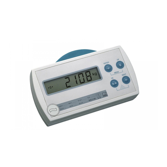
WE2108 3.1.1 WE2108 unit view The front of the WE2108 consists of the following elements: ENTER MENU NEXT WE2108 1. Display window with 5−digit numerical display and special symbols. 2. Keys for scale and menu functions. 3. Concealed button for access to the calibration menu. The button is accessi- ble with a pointed object (with the mark removed). -
Page 15: Display
WE2108 The inscriptions above the keys state the second function of the keys during parameter input (menu guidance). Activating the functions simultaneously pressing of ENTER MENU (Counting scale): simultaneously pressing of NEXT • Concealed button for access to the calibration menu (see WE2108 unit view). -
Page 16: Connections
WE2108 Connections The load cell and all control and supply cables are connected by means of screw terminals inside the housing. The terminals are equipped with wire pro- tection, the use of connector sleeves is recommended especially for the load cell cables. -
Page 17: Cable Entry
The PG glands serve solely for sealing and strain relief. The shield of the cable must therefore not be contacted to the PG gland (as in other HBM units), but to the screw clips in front of the connection terminals. -
Page 18: Process Outputs
WE2108 3.2.4 Process Outputs Terminal PC board legend Function Example of connection Pout3 not used Pout3 Pout2 Pout1 − Ground Pout2 Process output 2 Ground Pout1 Process output 1 Ground open−collector to ground, (external) U = 45 V, I = 200 mA typ. (electronically protected). When con- necting magnetic articles (e.g. -
Page 19: Rs−232 Interface (Only Rs−232 Versions)
Up to four load cells of 350 ohms (w 87 ohms burden) can be connected to the WE2108. HBM offers junction boxes of the types VKK1−4 or VKK2−6 for connecting the cables as well as for corner balancing (”corner load adjust- ment”) for scales with several load cells. -
Page 20: Installation
Electrical and magnetic fields frequently cause coupling of interference volt- ages into the measuring circuit. Use only shielded, low−capacitance measur- ing cables (measuring cables from HBM fulfil these conditions). Do not run the measuring cables parallel to power current and control cables. If this is not possible, protect the measuring cable (e.g. -
Page 21: Mounting On A Stand (We2108 In A Plastic Housing)
WE2108 Screws CLICK : Movement sequence of the wall mounting Abb. 4.2 Mounting on a stand (WE2108 in a plastic housing) Mounting on a stand is possible for free standing scales. This must have a plate for four holes according to Abb. 4.3 for fastening the WE2108. With cor- responding design, a concealed cable run inside the stand is possible. -
Page 22: Use As Desktop Unit (We2108 In A Plastic Housing)
WE2108 The unit is mounted in the following steps: 1. Remove the mounting base from the back of the housing after loosening two screws. 2. Fasten the mounting base to the stand plate with four screws with a diame- ter of 4 mm. 3. -
Page 23: Sealing / Calibration Ability
WE2108 Sealing / calibration ability According to the scale application, the scale electronic unit must be labelled and sealed. Different lettering strips are enclosed for use as non−automatic scale of class III and IIII. The following data must be stated on the lettering strip as a minimum: Maximum load of the scale Minimum load of the scale Scale interval... -
Page 24: Operation
WE2108 Operation All unit functions can be controlled in one or several of the following ways: • Operating front with 4 short stroke keys • Two programmable switching inputs • Coupling an external computer through the serial interface The keyboard controls directly the essential scale functions (gross/net , taring , zeroing and printing... -
Page 25: Basic Functions
WE2108 Basic functions 5.1.1 Switching on and off The unit is switched on after the supply voltage is applied. To switch off pro- ceed as follows: Scale Mode ENTER MENU NEXT WE2108 ENTER+UP (Cancel) Press simultaneously Unit switched off ENTER Main Menu 1) Switching back on with arbitrary key NOTE... -
Page 26: Taring
WE2108 5.1.3 Taring ( The current gross value is stored by pressing the key and deducted from all following weight values. The displayed (net) value is therefore zero directly after taring. The tare value can be read off in the InFO menu item under ”tArE”. -
Page 27: Display Lighting
WE2108 5.1.7 Display lighting Proceed as follows to switch the LCD background lighting on and off: Scale Mode ENTER MENU NEXT WE2108 ENTER+UP (Cancel) Press simultaneously (2x) ENTER Light ON / OFF Main Menu 5.1.8 External operating elements According to the configuration of the scale, the gross / net switch−over, taring and printing functions can also be operated by external switches (e.g. -
Page 28: 5.1.10 Parameter Setting
WE2108 Operation: 1. (Optional): Placing a container on the scale and taring. 2. Placing the reference quantity of the parts to be counted on the scale. This number is predetermined or must be changed in the parameter menu. Then activate the counting scale function as follows: Scale Mode ENTER MENU... -
Page 29: 5.1.11 Error Displays
WE2108 HINWEIS The major part of the parameters can also be entered through the PC− interface (RS−232 / RS−485). The CD−ROM available as accessory with the Order No. 1−WE2108/DOC contains apart from the complete docu- mentation (Reference Manual) of the unit also the setup program WE2108 Panel. -
Page 30: Menu Operation
WE2108 Menu operation 5.2.1 Menu Overview You reach the parameter menu (MENU) of the WE2108 by simultaneously pressing the ENTER keys. Here you can set unit function, limits, printing logs etc. and calibrate the scale characteristic. For better overview the param- eters are grouped in several submenus, which can be called up using the main menu. - Page 31 WE2108 6. Change the flashing place by pressing repeatedly. In the case of multi− digit values NEXT switches to the higher value digit, which can then also be changed with UP. 7. To accept the entered value now press ENTER. The entered value is rejected with and the previous value restored.
-
Page 32: Example: Setting The Parameter "Cap
WE2108 5.2.2 Example: Setting the parameter ”CAP 1” Scale Mode ENTER MENU NEXT WE2108 ENTER+UP Press simultaneously ENTER (Change) Accept ENTER NEXT... UP... ENTER UP... NEXT Number to be set flashes Submenu Parameter change Mainmenu (Cancel) The major part of the parameters can be reached through the described struc- ture of main and submenu. -
Page 33: Complete Menu Structure
WE2108 5.2.3 Complete menu structure ”Information” submenu Para- Meaning Value range Remarks meter CHEC Calibrtation counter 0 ... 99999 only display tArE Current tare value 0 ... 99999 Display of the current tare ENTER value. Change under ”P_tAr” S_Ver Software version only display NEXT F_nb... - Page 34 WE2108 ”Unit setting” submenu Para- Meaning Value range Remarks meter OFF_t Time for automatic 0: deactivated Time = ”OFF_t” * 20s switch−off (only with un- 1...99 ENTER loaded scale) Fin 1 Switching input 1 function 0: no function Only if input not occupied by 1: taring special function (see ”F_InP”...
- Page 35 WE2108 ”Filter settings” submenu Para- Meaning Value range Remarks meter F_FiL Digital filter setting Mesurement / Settling time −1 (3dB – cutoff frequency rate [s [ms] ENTER at ”Icr” = 0) 0: 13,0Hz 1: 12,5Hz 2: 11,2Hz NEXT 3: 07,5Hz 4: 03,0Hz 5: 02,5Hz 6: 02,0Hz...
- Page 36 WE2108 ”Scale function” submenu (only with access authorization!) Para- Meaning Value range Remarks meter LocPA Protection of the cal- Access allowed ibration parameters Access blocked ENTER F_tAr Taring function: 0: Normal 1: Preset tare unit Dimensional unit: 0: none NEXT 1: g 2: kg 3: t...
- Page 37 WE2108 ”Calibration” submenu (see Section 6 ”Calibration”) (only with access authorization!) Values can be changes manually or automatically measured with ENTER Para- Meaning Value range Remarks meter Linearization 0: off (2 Points) 0: Part load calibration 1: polynominal (3 points) possible ENTER 2: polynominal (4 points)
- Page 38 WE2108 Test functions for Service purposes Para- Meaning Remarks meter t_LCd Display−Test ENTER:Switching special segments on / off NEXT: Switch through test pattern (numbers) 00000, 12345 ,1 3 5, 2 3 , 8 , 88888, −−−−− t_IO Switching inputs / outputs UP: Process output 1 on / off test NEXT: Process output 2 on / off...
-
Page 39: Explanations For The Settings
WE2108 Summing functions Para- Meaning Remarks meter F_Add Switching the summing See Section 7.7 function on/off total Indication of sum, if nec. in two display phases for val- ues > 5 digits t_nbr Indication of summand counter clr_t Deletion of sum and summand counter Prtno Indication of running num-... - Page 40 WE2108 The following table shows the different operating modes of the unit and the calculation of the respective net values: Tare function Display mode Tare value display Calculation of the net value (InFO menu) ”F_tAr” 0 = normal Gross last tare value −...
-
Page 41: Standstill Criterion
WE2108 5.3.3 Standstill criterion The condition for a standstill indication can be set by means of the parameter ”StiLL” in the menu Func. The parameter values 00 to 29 are permitted in accordance with the following table (First digit = time interval, second digit = step width). Standstill is indicated when the measured value varies maximally by the pre- set step width within the time interval. -
Page 42: Calibration
WE2108 Calibration The scale is calibrated by setting the user characteristic on the WE2108, i.e. the scale electronics are adapted to the actual output signals which the load cell delivers with unloaded scale or at nominal weight. Calibration weights are required for this as a rule, as an alternative it is possible to enter the mea- sured values if these are known. -
Page 43: Part Load Calibration
WE2108 • Press ENTER to store the value. donE appears as confirmation. 4. Calibration weight: • To calibrate the nominal load, either a calibration weight equal to the scale nominal load ”CAP 1” is used, or a part load calibration is per- formed (see next section). -
Page 44: Special Applications
WE2108 Special applications Further functions having influence on the weight indication of the WE2108 are listed below. The settings can be relevant for legal for trade approval, there- fore changes are not possible with the access lock activated (exception: filter setting). -
Page 45: Calibration With Linearization
WE2108 Calibration with linearization The standard calibration with zero and final value is sufficient for the majority of scale applications (”Lin” = 0). Only if inadmissible errors occur in this process, the signal should be linearized (”Lin” = 1/2). Linearization corrects errors in scale attachments the output signal of which is not proportional to the weight (e.g. - Page 46 WE2108 1. Call up the menu. 2. Set the ”Lin” parameter (see following tables). 3. Zero value: • Call up the parameter ”CAL−0”, the previous calibration value is dis- played with ENTER. • Leave the scale unloaded. • Pressing ENTER again starts the measurement.
-
Page 47: Direct Entry Of The Characteristic Values
WE2108 For an optimum correction the calibration weight 1 should be in the range in which the greatest deviations of the characteristic occur: LOAd1 LOAd2 (Nominal load) Calibration at 4 points Parameter Action Value Linearization Set to ”Lin” = 2 CAL−0 Measure (scale unloaded) automatical measurement... -
Page 48: Calibrating With Calculated Values
WE2108 The method is suitable: • when building several equal scales, • for restoring the calibration after inadvertent deletion. A prerequisite is that the original values have been noted, • for calibrating with calculated values. Proceed as follows: • Select ”CAL−...” parameter in the menu and display with ENTER. -
Page 49: Influence Of The Geographical Installation Site
WE2108 Example: Parallel connection of 4 load cells of 20 t, sensitivity 2 mV/V. Nominal load of the scale 60 t, 6000 divisions, resolution step 0,01 t. 1. Setting the scale parameters in the Func menu: • Display unit (tonnes): ”unit”... -
Page 50: Access Authorization
WE2108 For this purpose enter in the Func menu (access authorization required !): • ”LAt” = the latitude • ”ALt” = the height above sea level in multiples of 100 m (e.g. 12 = 1200 m above sea level). A prerequisite for the correction calculation is that the values of the calibration location are entered before the calibration with calibration weights. -
Page 51: Pushbutton Lock
WE2108 Independently of this, every change relevant to legal for trade applications causes the calibration counter to be incremented in the case of legal for trade applications (i.e. in the OIML or NTEP mode, ”trAdE” parameter). In the indus- trial mode (”trAdE” = 0) the calibration counter remains unchanged. This is independent of the locking of the menu items by the ”LocPA”... -
Page 52: Dead Load And Nominal Value
WE2108 6.7.3 Dead load and nominal value: Adaptation to the dead load and possible part utilization (user characteristic) of the load cell takes place in the calibration of the scale in the parameter menu. The WE2108 processes the measured values internally with a higher accuracy than the display requires. -
Page 53: Further Functions
WE2108 Further functions Filtering The WE 2108 has flexible analog and digital filter functions, in order to obtain a stable measured value with a short transient time. The setting ex works is sufficient as a rule for scales with up to 6000 divisions at 1 μV/e. Changes are possible in the menu: •... -
Page 54: Limit Outputs
WE2108 Indication behaviour The measuring time can be a few seconds. As soon as a valid measured value was formed, this is displayed together with the measurement unit. Even if the animals continue to move the value continues to be displayed. The filter determines the weight which the platform would be subjected to in the case of non−moving animals. -
Page 55: Inputs
WE2108 Parameter Weight Limit status o. C. – switch Output level Px_Lo under switch−off value inactive closed over switch−on value activ open High under switch−off value inactive open High over switch−on value activ closed between switch−on Status remains and switch−off value unchanged The relevant output switches off on overcurrent. - Page 56 WE2108 Scale function for Input 1 (”Fin 1” parameter) F_InP Fin 1 Function 0; 2; 4; 6 None Taring Print Gross / Net Alternatingly for each activation: − Taring − Switching over to gross 1; 3; 5 −− no Scale function (input occupied with inclination switch) Scale function for Input 2 (”Fin 2”...
-
Page 57: Printing Function
WE2108 Printing function A printer can be connected to the serial interface of the WE2108 for outputting the weight values. The communication uses the XON / XOFF protocol. The interface must previously be set to the ”Printing” mode (”F_SEr” = 1 in the ioSEt menu). -
Page 58: Formatting Of The Printing Output
WE2108 Net (Preset tare): Date: 05.12.98 34,65 10,00 kg PT Counting scale (Gross): Date: 05.12.98 43 Pcs The printout occurs only at standstill, therefore the dimensional unit is always printed. It is possible to print as frequently as desired in an application which is not legal for trade. -
Page 59: Example
WE2108 7.5.1 Example ”F_Prt” 2 (Date; Measured value) ”Art_No” 1234 ”SPACE” ”LnEF1” ”LnEF2” −−−−−−−−−−−−−−−−−−− > > >>>>Date: 05.12.98 >>>>Art−No: 1234 >>>>G 34,65 > > > −−−−−−−−−−−−−−−−−−− (The characters ”>” and ”−” are not printed.) Printer-specific control codes can be automatically inserted prior to or after printing (e. -
Page 60: Functions In The Menu Add (New)
WE2108 After summing has been effected, the text AddEd appears in the display for 1 second. If there is no standstill condition when the key is operated, the request is stored and executed after the standstill has been reached (summing and, if nec., printing). -
Page 61: Deletion Of The Sums
WE2108 The value added is always the display value, switchover gross/net is possible between several summands! The sum of all values as well as the number of summands is stored. It is not possible to subtract the most recent value! A maximum of 21000 values are added. -
Page 62: Print
WE2108 • Sum and counter remain unchanged • The display does not show the note added • If the print function is active, the current weight value is printed, plus the note No count value not added For adding weight values, the counting scale function must be generally deac- tivated. -
Page 63: Interface For Large Display (Second Display)
WE2108 Interface for large display (second display) Output (1−2 values / second) is effected by the interface, if ”F_SEr” = 3 is set (in the menu ioSEt). Output format for second display: Byte no. Character output Remarks Start character (ST_CH) If set (ioSEt−menu) or space character (otherwise) -
Page 64: Troubleshooting
WE2108 Troubleshooting Error message Meaning Remedy Measured value above the max. Reduce load of the scale display range (depending upon the Test set nominal load: ”CAP 1”, ”CAP 2” (marks above) set scale standard) parameters in the Func menu Measured value below the min. For net display: switching over to gross display range (depending upon the possible recalibration... - Page 65 WE2108 Error on output of the transmit Report to manufacturer buffer Overflow of the reception buffer on Send commands from external software at PC interfacing larger interval Overflow of the watchdog timer Report to manufacturer Inadmissible interrupt Report to manufacturer Loss of unit parameters in the non- Report to manufacturer volatile memory...
-
Page 66: Specifications
WE2108 Specifications Specifications WE2108 in ABS−housing Type WE 2108 Max. number of scale intervals acc. to 6000; 2x3000; Multi-Range; Multi-Interval OIML R76 (Class III, IIII) μV/e ≥1 Input sensitivity Multi-Range mV/V 0 ... 2,7 Ω Min. input impedance of the load cell Ω... -
Page 67: Dimensions We2108 In Abs−Housing
WE2108 Dimensions WE2108 in ABS−housing View X ENTER 12° MENU NEXT WE 2108 12° Dimensions (in mm) A1632-2.0 en... -
Page 68: Specifications We2108S/We2108M In Steel−Housing
WE2108 Specifications WE2108S/WE2108M in steel−housing Types (with RS-232-Interface): WE2108S; WE2108M (with RS-485-Interface): WE2108S−485; WE2108M−485 Max. of scale intervals acc. to OIML R76 6000; 2 x 3000; (Class III, IIII) μV/e Multi-Range; Multi-Interval ≥1 Input sensitivity Measuring range mV/V 0 ... 2.7 Ω... -
Page 69: Dimensions We2108S/We2108M In Steel−Housing
WE2108 Dimensions WE2108S/WE2108M in steel−housing WE2108S (Wall mounting or Desktop unit) WE2108M (Panel mounting) ENTER ENTER MENU MENU NEXT NEXT Cable fitting 5 x Pg7 Detail X Detail X ∅ 8 ∅ 4 Dimensions (in mm) A1632-2.0 en... - Page 70 WE2108 A1632-2.0 en...
- Page 72 They are not to be understood as a guarantee of quality or dura- bility. Hottinger Baldwin Messtechnik GmbH Postfach 10 01 51, D-64201 Darmstadt Im Tiefen See 45, D-64293 Darmstadt Tel.: 06151 803-0 Fax: 06151 8039100 Email: support@hbm.com Internet: www.hbm.com A1632-2.0 en...
Need help?
Do you have a question about the WE2108 Series and is the answer not in the manual?
Questions and answers