
Related Manuals for Solarwize SWF850

Summary of Contents for Solarwize SWF850
- Page 1 User Manual Enerwise Solutions Ltd. EMAIL: sales@enerwise.asia Copyright © 2013 Enerwise Solutions Ltd. All rights reserved.
- Page 2 1. Add 4.12 for description of setting page of web. 2. Add 4.11 for description of demo page of web 3. Add 4.5.4 for description of Real-time page of 4. Add section 6 for description of Quick Start Solarwise SWF850 QuickStart/Troubleshooting Manual 2 / 73...
-
Page 3: Table Of Contents
4.4 Title ........................... 21 4.5 Summary ........................... 22 4.5.1 Summary ........................22 4.5.2 Power ..........................23 4.5.3 Energy ..........................24 4.5.4 Real-Time ........................25 4.5.5 Events ..........................27 4.6 AC Network ........................28 Solarwise SWF850 QuickStart/Troubleshooting Manual 3 / 73... - Page 4 5.2 Sending Data Packets to the Cloud Server ................ 65 6. Quick Start ..........................66 7. Troubleshooting ........................69 7.1 IE Compatibility Issue ......................69 7.2 DNS Setting for Email Alarms .................... 72 7.3 Other Communication Problems ..................72 Solarwise SWF850 QuickStart/Troubleshooting Manual 4 / 73...
-
Page 5: Introduction
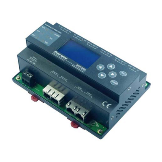
1. Introduction 1.1 Product Introduction SWF850 is an all in one PV analyzer that acts as a data collector by connecting to devices that exist in a typical Solar Energy generating facility. Inverter protocols are read through the Ethernet or Serial port and events or data will be processed by SWF850 and the SolarWise Cloud Server. -
Page 6: Hardware Structure & Installation
Note2: Damage due to over overvoltage or overcurrent! The SWF850 has a rated tolerance for each input types, each tolerance level is different depending on the input type, it is absolutely necessary to double check the specifications of each input to avoid damage. -
Page 7: Product Dimensions
2.4.1 Ensuring the Unit is used in a Correct Environmental Condition Installed Location Indoor Mounting Standard DIN 35mm Rail Mount Operating Temperature DC power supply version: -20 to +70℃ Storage Temperature -30 to +80℃ Relative Humidity 5% to 95% Solarwise SWF850 QuickStart/Troubleshooting Manual 7 / 73... -
Page 8: Connecting The Power Supply Input
Power 2.4.3 Connecting the Analog Input (AI) SWF850 has a total of 6 analog inputs AI1 to AI6, and AI1 to AI4 are applied for current signal input, AI5 to AI6 are applied for voltage signal input. AI1 to AI4 input connectors for SWF850 are shown respectively below. The terminals marked “AI1”... - Page 9 The connection method between AI1-AI4 and four-wire sensors is described as below. 4-Wire Type 24V AI4 24V 24V AI1 Sensor 24VDC SWF850 Sensor Power Input AI5 to AI6 applied for voltage signal input are shown as below. Solarwise SWF850 QuickStart/Troubleshooting Manual 9 / 73...
-
Page 10: Connecting To The Digital Input (Di)
2.4.4 Connecting to the Digital Input (DI) SWF850 has a total of 6 digital inputs DI1 to DI6, DI_Vout is the built-in internal excitation voltage of 15V. DI input can be set to status input for monitoring the status of SPD or MCCB, also can be set to pulse input for energy collection. -
Page 11: Connecting To An External Revenue Meter
“Kt” pulses which usually one pulse represents a certain amount of kWh measured in the meter. Hence, by collecting such pulse from the meter will allow SWF850 logger to cumulate the actual energy measured by this meter. Below shows the digital input DI connector image:... -
Page 12: Connecting To The Digital Output (Do)
For this procedure, please goto section 4.12.6.1. 2.4.6 Connecting to the Digital Output (DO) SWF850 has one mechanical relay digital output, as shown in Figure below. Relay OUT NO NC DO Type... -
Page 13: Connecting The Ethernet
RX and TX LED lights will flash red and yellow respectively upon serial communications. Alarm LED is lid when there is an alarm set point of SWF850 triggered in the system, this may sometimes be due to incorrect AI alarm setting used so that over or under set points are triggered. -
Page 14: Panel Function
3. Panel Function 3.1 Keys Operation SWF850 has six membrane keys: “↑”, “↓”, “←”, “→”, “Enter”, “Esc”. “↑”, “↓”, “←”, “→”: Used for selecting menu, the selected menu will be highlighted; they also can be used to change the value of parameters. -
Page 15: Measurements
Total kWh Measurements of other AC meters AC meter Export energy Today / Total Import energy Today / Total Load energy Today / Total Measurements of Analog. Analog Input Status Display digital status. Solarwise SWF850 QuickStart/Troubleshooting Manual 15 / 73... -
Page 16: Setting
1. Ethernet1/Ethnet2 DHCP: Set DHCP server Enable/Disable. IP: Set fixed IP address when DHCP = Disable. Gateway: Set gateway address when DHCP = Disable. Subnet mask: Set fixed subnet mask when DHCP = Disable. Solarwise SWF850 QuickStart/Troubleshooting Manual 16 / 73... - Page 17 When DI of SWF850 device is input AC kt pulse from other meter, DI pulse input direction can be set as Import/Export/Load. 2. DI Kt: When DI of SWF850 device is input AC kt pulse from other meter, it is the const value for AC kt pulse to be set. Solarwise SWF850 QuickStart/Troubleshooting Manual...
-
Page 18: Maintenance
Language, Time Zone, Date & Time setup, Display setup, Relay Control, Authorization, Password, AI adjustment. Maintenance Language Set display language. Time Zone Set time zone of swf850. Date & Time Set system date and time. Date Time Display setup Set the contrast of LCD. -
Page 19: Device Info
LAN1 is set to DHCP = Enable. LAN2 is set to fixed IP address: DHCP= Disable, IP=192.168.1.100, Sub mask=255.255.255.0, Gateway=192.168.1.1. All of the connect device configuration information will be cleared. CommuSchedule will be stopped. Solarwise SWF850 QuickStart/Troubleshooting Manual 19 / 73... -
Page 20: Overview Of Web
4.1 Browser Request After the cable is plugged in the Ethernet port and the IP address is set by LCD, user can use web browser to login the build-in Web management system of SWF850 by the link like: http://192.168.1.100/. There are some requirements for the client browsers, currently support the browser version is as... -
Page 21: Menu
The users will log out after clicking the “Logout System”, just as its name implies. Title Solarwise SWF850 QuickStart/Troubleshooting Manual 21 / 73... -
Page 22: Summary
Import, Export, or Load, the other one is for period type of this week, the last 6 months, the last 12 months, and all years. The graph plots the bar every day on “this week”. The graph plots the bar every month on “6 month” and “12 month”. Solarwise SWF850 QuickStart/Troubleshooting Manual 22 / 73... -
Page 23: Power
For example, after the users select the ArrayBox#01 and ArrayBox#02, they can’t select the inverter or string any more. Then, clicking the “generate”, the bar graph will show on the left hand. Solarwise SWF850 QuickStart/Troubleshooting Manual 23 / 73... -
Page 24: Energy
The function for expected power range could be enabled or disabled in the “Setting-> Global Setting -> kW/kWh @ Irradiation Range” and so does the range. 4.5.3 Energy All the energy generated by critical equipments can be show on the power view graph. Solarwise SWF850 QuickStart/Troubleshooting Manual 24 / 73... -
Page 25: Real-Time
The “print” button is used for print the graph, the “download” button is used for download PNG, PDF or CSV document. Solarwise SWF850 QuickStart/Troubleshooting Manual 25 / 73... - Page 26 SolarWise PV Farm Management System SWF 850 User Manual Solarwise SWF850 QuickStart/Troubleshooting Manual 73 / 73...
Need help?
Do you have a question about the SWF850 and is the answer not in the manual?
Questions and answers