Advertisement
Quick Links
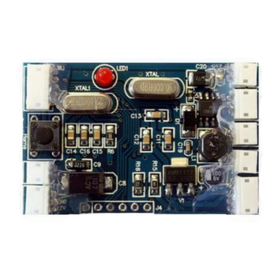
SUPPO OSD V3.71
10HZ/current sensor
Connetion Pins
Connector's description
To the add-on
Current
sensor
Current sensor
from SUPPO
Config panel
Connect to
button panel
Video In
To you
Camera
GPS
To the GPS
unit supplied
Configuring OSD:
"Menu"
on "Config Panel" to enter system configuration
Press button
Use "Option SW" and "Select" button to configure
Connect to your radio receiver's
RSSI
RSSI port
Main Batt
Connect to your airplane's battery
(to RC plane's
pack (monitor plane's voltage
battery)
Max 28V).
As 11.7v shown on left)
Video out
For the OSD video output
Power in
Connect to power source for your
OSD
(as Voltage 4.5V shown on left)
Advertisement

Related Manuals for SUPPO OSD V3.71

Summary of Contents for SUPPO OSD V3.71
- Page 1 SUPPO OSD V3.71 Connetion Pins 10HZ/current sensor Connector’s description To the add-on Connect to your radio receiver’s Current RSSI sensor Current sensor RSSI port from SUPPO Config panel Connect to Main Batt Connect to your airplane’s battery button panel (to RC plane’s pack (monitor plane’s voltage...
- Page 2 Connect RSSI to your RC Receiver (Warning: potential dangerous, could damage your RX. not recommend to do so if you don’t well understand your Radio RX) Connect 9-12V power to Suppo V-tx to power up Suppo V-Tx, OSD and the camera. Important Notice, care fully check the power wire connect Camera, OSD and Video Tx.
- Page 3 Specifications: Input Volt Weight Size Setting RSSI Min – Max value: 5-12V 49*33*6.5m 3.3V On ground power up TX and RX, press “set home” button, OSD will record RSSI Current Sensor 7-35V, 100A 31*35mm Max; Power consumption: Max:1.1W Plane battery detect max 28V On ground, power off TX, press “Menu”...
Need help?
Do you have a question about the OSD V3.71 and is the answer not in the manual?
Questions and answers