
Related Manuals for HAUVREX HFL4140E

Summary of Contents for HAUVREX HFL4140E
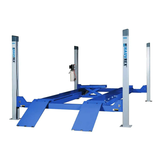
- Page 1 ELECTRO-HYDRAULIC 4-POST LIFT Installation/Operation & Maintenance Manual MODEL: HFL4140E Version: HR201408.2.0...
- Page 3 Please read this instruction carefully for safe and proper use of the car lift, and keep it handy for future reference. ■ This Manual is for model: HFL4140E ■ As for the assurance of safety in design and construction of car lift, read this Manual first.
-
Page 5: Table Of Contents
Installation/Operation & Maintenance Manual HFL4140E 4-POST ALIGNMENT LIFT TABLE OF CONTENTS TABLE OF CONTENTS Chapter 1 DESCRIPTION OF THE MACHINE 1.1 FIXED STRUCTURE ASSEMBLY 1.2 MOVABLE STRUCTURE Chapter 2 SPECIFICATIONS 2.1 OVERALL DIMENSIONS 2.2 TECHNICAL SPECIFICATION 2.3 ELECTRIC MOTOR 2.4 HYDRAULIC PUMP 2.5 OIL... - Page 6 Installation/Operation & Maintenance Manual HFL4140E 4-POST ALIGNMENT LIFT TABLE OF CONTENTS APPENDIX B HYDRAULIC DIAGRAM APPENDIX C ELECTRICAL WIRING DIAGRAM APPENDIX D SPARE PARTS...
-
Page 7: Chapter 1 Description Of The Machine
Installation/Operation & Maintenance Manual HFL4140E 4-POST ALIGNMENT LIFT Operator side: this is the front of the lift, including Chapter 1 DESCRIPTION OF THE the area reserved for the operator with the control MACHINE panel. The operator side is opposite the vehicle access side. -
Page 8: Movable Structure
Installation/Operation & Maintenance Manual HFL4140E 4-POST ALIGNMENT LIFT Each cross-piece translates vertically between two posts. Fig. 3 The drive post mounts the hydraulic power unit (Fig. Fig. 5 As shown in Fig. 5, the ends of the cross-pieces are fitted with the following parts: Return pulleys (Fig. - Page 9 Installation/Operation & Maintenance Manual HFL4140E 4-POST ALIGNMENT LIFT Both platforms have inside rails (Fig. 6-6) for rolling jack, and fixed wheel stops (Fig. 6-7) to stop the vehicle from going beyond the ends of the platforms. The access ramps (Fig. 6-4), pivoted to the...
-
Page 10: Chapter 2 Specifications
Installation/Operation & Maintenance Manual HFL4140E 4-POST ALIGNMENT LIFT Chapter 2 SPECIFICATIONS 2.1 OVERALL DIMENSION Fig. 8 Overall Dimension... -
Page 11: Technical Specification
Installation/Operation & Maintenance Manual HFL4140E 4-POST ALIGNMENT LIFT 2.2 TECHNICAL SPECIFICATION Driving Mode Electro-hydraulic Capacity 4000kg Max. Lifting Height 1800mm Min. Height 135mm Platform Length 4500mm Platform Width 500mm Lifting Time ≤60S Lowing Time ≤50s Overall Width 3254mm Overall Length... - Page 12 Installation/Operation & Maintenance Manual HFL4140E 4-POST ALIGNMENT LIFT HYDRO OIL 32; SHELL TELLUS T37 or an Min. (mm) Max. (mm) equivalent oil. 2300 4500 2000 2.6 TYPES OF VEHICLES SUITABLE FOR B E I N G LI F T E D...
-
Page 13: Chapter 3 Safety
Installation/Operation & Maintenance Manual HFL4140E 4-POST ALIGNMENT LIFT Chapter 3 SAFETY It is extremely important to read this chapter of the manual carefully and from beginning to end as it contains important information regarding the risks the operator or maintenance fitter may be exposed to if the lift is used incorrectly. - Page 14 Installation/Operation & Maintenance Manual HFL4140E 4-POST ALIGNMENT LIFT DANGER: indicates imminent danger that can result in serious injury to people or death. WARNING: indicates situations and/or types of maneuvers that are unsafe and can cause more or less harmful injuries or death.
- Page 15 Installation/Operation & Maintenance Manual HFL4140E 4-POST ALIGNMENT LIFT Fig. 18 Should the steel cables slacken or break, the safety Fig. 15 wedges will stop the movable part of the lift and the POTENTIAL RISKS DURING LIFTING vehicle in its current position (Fig. 19).
- Page 16 Installation/Operation & Maintenance Manual HFL4140E 4-POST ALIGNMENT LIFT This hazard may arise in the case of incorrect positioning of the vehicle on the platforms, incorrect stopping of the vehicle, or in the case of vehicles of dimensions that are not compatible with the capacity of the lift.
- Page 17 Installation/Operation & Maintenance Manual HFL4140E 4-POST ALIGNMENT LIFT requirements. Reduce the risk of slipping by wearing It is therefore essential to adhere scrupulously to all safety shoes. regulations regarding use, maintenance and safety contained in this manual. Fig. 25 RISK OF ELECTRIC SHOCK Fig.
-
Page 18: Chapter 4 Installation
Installation/Operation & Maintenance Manual HFL4140E 4-POST ALIGNMENT LIFT vehicle itself and the nearest fixed or mobile Chapter 4 INSTALLATION structures in the workshop. FOLLOWING OPERATIONS MUST Check: PERFORMED EXCLUSIVELY BY SPECIALISED Height: 5000 mm min. (calculate also the height TECHNICAL... -
Page 19: Assembly Of Movable Structure (Platform)
Installation/Operation & Maintenance Manual HFL4140E 4-POST ALIGNMENT LIFT reinforcing mesh, thickness min. 180 mm and properly leveled. Fig. 28 4 . 1 A S S E M B L Y M O V A B L E STRUCTURE (PLATFORM) Fig. 30 5 - Place the movable platform (Fig. - Page 20 Installation/Operation & Maintenance Manual HFL4140E 4-POST ALIGNMENT LIFT Position the posts at the end of the cross-pieces observing the numbering and the lay-out shown in Fig. 29. Fit the safety rods (Fig. 35-1) from the top of the posts, inserting them between the rear face of the cross-pieces and the guide pins (Fig.
-
Page 21: Hydraulic System Connection
Installation/Operation & Maintenance Manual HFL4140E 4-POST ALIGNMENT LIFT Screw the nuts and washers onto the terminal motor rotation direction: it should be the same of the blocks. During this procedure, make sure that the one on the plate of the motor. -
Page 22: Secure The Posts To The Ground
Installation/Operation & Maintenance Manual HFL4140E 4-POST ALIGNMENT LIFT Press LIFT button and complete the lift cycle. During the cycle, check that the cross-pieces slide freely and without undue rubbing friction (you may want to stop the lift motion every 20 or 30 cm to make this inspection easier). -
Page 23: Adjusting The Lifting Cables
Installation/Operation & Maintenance Manual HFL4140E 4-POST ALIGNMENT LIFT Fit the ramps by slotting them into the platforms on N.B. If there is insufficient oil, top up the the required end and then fix the wheel stops on the reservoir to the correct level. -
Page 24: Chapter 5 Operating Principles And Use
Installation/Operation & Maintenance Manual HFL4140E 4-POST ALIGNMENT LIFT Chapter 5 OPERATING PRINCIPLES AND USE Fig. 47 5.1 MAIN MACHINE OPERATION LIFTING Press the LIFTING button until the lift reaches the desired height. During its travel, the safety wedge release lever will Fig. -
Page 25: Rolling Jack Operation
Installation/Operation & Maintenance Manual HFL4140E 4-POST ALIGNMENT LIFT 5.2 ROLLING JACK OPERATION Chapter 6 MAINTENANCE Turn the 3-way control valve on the power pack to IIMPORTANT the left. Other lifting and lowering operations are the For a longer life of the platforms preserving their same to the main machine. - Page 26 Installation/Operation & Maintenance Manual HFL4140E 4-POST ALIGNMENT LIFT guidelines and should be construed as the hole until the oil is at the recommended level. maximum intervals between each intervention. Refer to Page 5 “SPECIFICATIONS” for information on the type of oil to use.
- Page 27 Installation/Operation & Maintenance Manual HFL4140E 4-POST ALIGNMENT LIFT Refit the drain plug. change the cables, CONTACT YOUR NEAREST ■ AUTHORISED SERVICE CENTRE. Fill the reservoir through the filler hole on the ■ top. 3 - HYDRAULIC PUMP Make sure the oil is filtered.
-
Page 28: Chapter 7 Troubleshooting
Installation/Operation & Maintenance Manual HFL4140E 4-POST ALIGNMENT LIFT Chapter 7 TROUBLESHOOTING PRECAUTIONS indicated Chapter “MAINTENANCE” and Chapter 3 “SAFETY”. Troubleshooting possible repairs require absolute compliance with ALL THE SAFETY Problem Possible cause Solution Burnt fuse ■ The lift does not rise when... -
Page 29: Appendix A Special Information
Installation/Operation & Maintenance Manual HFL4140E 4-POST ALIGNMENT LIFT A P P E N D I X S P E C I F I C INFORMATION DISPOSAL OF USED OIL Used oil drained from the reservoir of the hydraulic power unit during oil changes is to be treated as a pollutant in accordance with the legislation in force in the country where the lift is installed. - Page 30 Installation/Operation & Maintenance Manual HFL4140E 4-POST ALIGNMENT LIFT APPENDIX B HYDRAULIC DIAGRAM...
- Page 31 Installation/Operation & Maintenance Manual HFL4140E 4-POST ALIGNMENT LIFT APPENDIX C ELECTRICAL WIRING DIAGRAM 3 Ph...
- Page 32 Installation/Operation & Maintenance Manual HFL4140E 4-POST ALIGNMENT LIFT APPENDIX D SPARE PARTS SPARE PARTS replacement parts repair interventions require the full observance of ALL SAFETY PRECAUTIONS listed in chapter 6 “Maintenance” and chapter 3 “SAFETY. Take all necessary steps to AVOID POWERING UP THE LIFT INADVERTENTLY.
- Page 33 Installation/Operation & Maintenance Manual HFL4140E 4-POST ALIGNMENT LIFT 86/87 103/104 97/98/99 86/87 86/87 88/89 86/87 89/90 86/87...
- Page 34 Installation/Operation & Maintenance Manual HFL4140E 4-POST ALIGNMENT LIFT 40/41/52 82/83 74/75 54/55 56/57 69/70/70.1 36/37 59/60 40/41 61/61.1 75.1 75.2 64/65 44/45...
- Page 35 Installation/Operation & Maintenance Manual HFL4140E 4-POST ALIGNMENT LIFT...
- Page 36 Installation/Operation & Maintenance Manual HFL4140E 4-POST ALIGNMENT LIFT PARTS LIST Chart No. Description QTY. Remarks SGM-801-01A-00 column 1 jointing parts SGM-801-01BC-00 column 2 jointing parts SGM-801-01D-00 column 3 jointing parts SGM-803-01A-00 runway 1 jointing parts SGM-803-01A-00 runway 2 jointing parts...
- Page 37 Installation/Operation & Maintenance Manual HFL4140E 4-POST ALIGNMENT LIFT PARTS LIST Chart No. Description QTY. Remarks SGM-804-01-00 Safty transmission pole GB70-85 Inner hexangular screw M6X20 SGM-804-11 Safty handle spindle φ15/Q235 SGM-804-09 Connection SGM-804-10 Connection 1 SGM-802-08 Orientation board SGM-802-07 Rubber block...
- Page 38 Installation/Operation & Maintenance Manual HFL4140E 4-POST ALIGNMENT LIFT PARTS LIST Chart No. Description QTY. Remarks GB6170-86 hexangular nut GB95-85 flat washer C GB91-86 D4X45 snap ring SGM-805-05-00 Cable stable jointing parts SGM-805-13 cable block 2 SGM-805-12 cable block 1 GB70-85...
Need help?
Do you have a question about the HFL4140E and is the answer not in the manual?
Questions and answers