Table of Contents
Advertisement
Quick Links
Advertisement
Table of Contents

Related Manuals for Direct Airscale SPACE WALKER ELECTRO

Summary of Contents for Direct Airscale SPACE WALKER ELECTRO
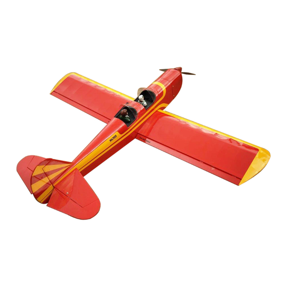
- Page 1 Direct Airscale scale model Code : 4131 TECHNICAL INSTRUCTIONS May change without notice space walker electro install Kit SERVOS Ailerons Rudder + wheel Elevator ASYMM 1.58m 1.16m install Kit Flaps Retract Gas or bec 41dm 2.1kg 2.9kg...
-
Page 2: Additional Items Required
CONGRATULATIONS. Thank you for choosing a Direct Airscale model. If you have any problems do not hesitate to consult our website. Especially the section CLUB DA (Direct Airscale club) for each plane where you will find information. You also can consult me directly by phone but try to be a maximum shorter . -
Page 3: Hinging The Aileron
4) Deflect the aileron and completely satu- HINGING THE AILERON. rate each hinge with thin C/A glue. The ailer- ons front surface should lightly contact the Note : The control surfaces, including the ai- wing during this procedure. Ideally, when lerons, elevators, and rudder, are pre- the hinges are glued in place, a 1/64”... -
Page 4: Hinging The Elevator
Tail fin bottom. Turnbuckle. Note : Work the aileron up and down sev- eral times to “work in” the hinges Horizontal fin bottom. and check for proper movement. HINGING THE RUDDER. HINGING THE ELEVATOR. Glue the rudder hinges in place using the Glue the elevator hinges in place using the same techniques used to hinge the ailerons. -
Page 5: Installing The Aileron Linkage
4) Using a 1mm drill bit and the control horns as a guide, drill the mounting holes through the aileron halves. 5) Mount the control horns by inserting the screws through the control horn bases and aileron halves, then into the mounting back- plates. -
Page 6: Horizontal Stabilizer
Right side. Wire keeper. Servo arm. Left side. Elevator servo. Rudder servo. HORIZONTAL STABILIZER. Repeat the procedure for the other aileron 1) Using a ruler and a pen, locate the center- servo. line of the horizontal stabilizer, at the trailing edge, and place a mark. -
Page 7: Vertical Stabilizer Installation
6) When you are sure that everything is aligned correctly, apply C/A glue to the top and bottom of the stabilizer mounting area and to the stabilizer mounting platform sides. 4) With the stabilizer held firmly in place, use a pen and draw lines onto the stabilizer where it and the fuselage sides meet. -
Page 8: Control Horn Installation
Vertical Stabilizer. Horizontal 90º Stabilizer. Hinge. C/A glue. Pen. When cutting through the covering to remove it, cut with only enough pressure to only cut through the covering itself. Cut- ting into the balsa structure may weaken it. CONTROL HORN INSTALLATION. Control horn installation as same as meth- od of aileron wing. -
Page 9: Pushrod Installation
INSTALLING TAIL STRUT SYSTEM. Elevator control horn. The tail strut system assembly follow pic- tures below. Rudder control horn. Plastic trap. PUSHROD INSTALLATION. Pushrod install as same as method of push- rod os aileron. See pictures below. Pushrod. Plastic trap. Pushrod. - Page 10 2) Using a pen, mark the locations of the two mounting screws. Remove the tail wheel Control clasp. bracket and drill 1mm pilot holes at the loca- tions marked. 3) Secure the tail wheel bracket in place us- ing two 3x10mm wood screws. Be careful not to overtighten the screws.
- Page 11 (2) Washer. Wheel Collar. (2) Washer. (2) Wheel Collar. Axle. Nut. Axle. Nut. Nut. Wheel. Wheel. Landing Gear. Nut. Wheel Pant. Landing gear. 3) You have to trim each axle using a tool cutting and cut-off wheel. Caution when cutting the axles and wear protective goggles.
-
Page 12: Installing The Main Landing Gear
4) A drop of C/A glue on the wheel collar screws will help keep them from coming lose Blind nut. during operation. Repeat the process for the other wheel. INSTALLING THE MAIN LANDING GEAR. MOTOR BOX. 1) The blind nuts for securing the landing gear are already mounted inside the fuselage. -
Page 13: Installing The Battery
INSTALLING THE BATTERY. See pictures below : 3x10mm Speed control. Battery. Secure the cowl with the screw provide with hardware. Tie wrap or rubber band. DUMMY ENGINE INSTALLATION. COWLING INSTALLATION. See pictures below : See pictures below : Trim and cut. Glue. -
Page 14: Installing The Receiver
INSTALLING THE RECEIVER. PILOT INSTALLATION. 1) Remove the fastening wire as same as pic- ture below. Receiver. Fastening wire. Tie wrap. Antenna wire. 2) Glue the pilot into the position. WINDSHIELD INSTALLATION. Glue. Glue. 2x8mm Machine screw. -
Page 15: Control Throws
ATTACHMENT WING-FUSELAGE. Bolt the wing to fuselage. 7.5 - 8 cm Wing tube. BALANCING. 1) It is critical that your airplane be balanced Insert two wing panels as pictures below. correctly. Improper balance will cause your plane to lose control and crash. The center of gravity is locate back from the leading edge of the wing, measured at wing ROOT. - Page 16 If you follow these guidelines from the common sense you go in with a lot of fun in the world of model airplanes. The Direct Airscale team wishes you good flights DA a large Vietnamese experience for flying scale airplanes...
Need help?
Do you have a question about the SPACE WALKER ELECTRO and is the answer not in the manual?
Questions and answers