Table of Contents
Advertisement
Advertisement
Table of Contents

Related Manuals for Fonrich FR-DCMG-MMPS

Summary of Contents for Fonrich FR-DCMG-MMPS
- Page 1 User Manual Version 1.5 DC System Monitor: FR-DCMG-MMPS Scan the code to learn more Fonrich (Shanghai) New Energy Technology Co., Ltd. Add: 1st Floor, Building 5, No.999 Jiangyue Road, Minhang District,Shanghai Web: www.fonrich.com Tel: +86 21 61679671 Email: sales@fonrich.com...
-
Page 2: Table Of Contents
Table of Contents Table of Contents ................................1 1 Documentation statement ............................... 3 2 Safety Precautions ................................3 2.1 Signs ..................................3 2.2 Safety Precautions ..............................3 2.3 Personnel requirements ............................3 2.4 Electrical connection ..............................4 2.5 System running ................................ 4 3 Product description ................................. - Page 3 6.5.3 Arc alarm time ............................16 6.6 Combined alarm strategy (closed by default, follow the steps below when needed) ..........16 7 MODBUS Protocol Definition ............................. 17 7.1 Communication format configuration ........................17 7.2 Data frame format description (refer to Modbus RTU standard) ................17 7.2.1 Data message example ..........................
-
Page 4: Documentation Statement
1 Documentation statement This manual applies to the product model FR-DCMG-MMPS, and the software version is A08D. 2 Safety Precautions 2.1 Signs The following signs may appear in this article, and their meanings are as follows. Signs Instructions Indicates a hazardous situation which,if not avoided, will result in DANGER death or serious injury. -
Page 5: Electrical Connection
Please read this user manual carefully before installation. If the equipment is damaged due to failure to install in accordance with this user manual, our company reserves the right not to guarantee the quality. Before installation, make sure that it is not electrically connected and powered on. ... -
Page 6: Product Description
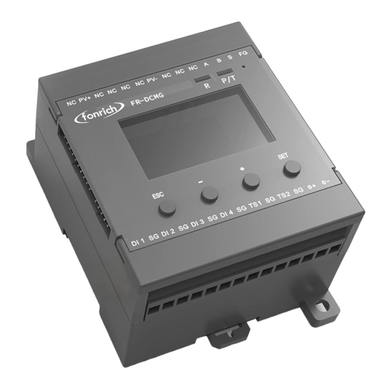
3 Product description FR-DCMG DC monitor products are mainly used in DC transmission, power distribution and other occasions, such as photovoltaic combiner boxes, arc protection boxes, etc. Through RS485 communication with the host computer, its main functions include real-time monitoring of the current of each branch in the DC system, the temperature of the cabinet, the status of the lightning arrester and the status of the DC circuit breaker, etc. -
Page 7: Terminal Definition
3.2 Terminal Definition Symbol Meaning PV+/PV- Measuring voltage Not connecion Not connecion RS485 Communication terminal Fixed Ground terminal TS1/TS2 Externally connected temperature sensor terminals Temperature sensor and digital input ground terminal DI1/DI2/DI3/DI4 4 digital input terminals O+/O- Connecting the shunt release Can connect modules with FUC interface Modules with an FMB interface can be connected, such as the FR- DCMG-AS4A DC Arc Detector. -
Page 8: Wiring Diagram Of Monitoring Module
4 Wiring diagram of monitoring module 4.1 Electrical wiring diagram Note: O+ is connected to 24V+, SG is connected to 24V-, if the connection is reversed, the module may be damaged... -
Page 9: Ground Connection And Rs485 Communication Shielded Wire
4.2 Ground connection and RS485 communication shielded wire The FG terminal of the FR-DCMG must be grounded, otherwise communication will interfere and the reliability of the device will decrease. The grounding wire should be grounded nearby. The grounding wire should be no more than 15cm from the “FG” terminal to the bottom of the combiner box. -
Page 10: Ui Introduction
5 UI introduction 5.1 Key operation FR-DCMG-MMPS has four keys "ESC", "-", "+", and "SET". "ESC" key is used to return to the default interface and cancel parameter settings; "SET" key is used to enter the parameter setting mode, select the parameter to be set and complete the setting of the parameter;... -
Page 11: Channel Current Data
⑥ Current histogram; the default display range is -4A ~ 20A, and the display range can be expanded by setting register 0x0B16; ⑦ Histogram partition: because 6 Halls are inserted, 6 partitions 5.4 Channel current data In the current interface, press the "+" or "-" key to enter the channel current display interface, and the current value of each channel is displayed on the screen. -
Page 12: Trip Self-Test Setting Interface
5.5.3 Press the "+" key to continue to select downwards to the arc parameter setting interface: MOD: Arc protection mode (Cont: continuous Arc Alarm mode, Single: Instantaneous Arc alarm mode) THR: Arc threshold (default 50) IAT: 2 (Instantaneous Arc Time, default 2) 5.5.4 Press the "+"... -
Page 13: Current Calibration Setting Interface
(Factory default)Relay mode (O+/O- DC voltage is 24v), the interface is as follows: On the shunt trip setting interface, you can set the shunt trip enable time (TIME) and trip self-check (SELFCHECK) when an arc alarm occurs. When the "*" flashes in the TIME line, press the "SET" key, and then press"+"or"-" to modify the shunt release time. -
Page 14: Alarm Status Display Interface
HV:— SV:Software version number ST:— 5.9 Alarm status display interface Alarm messages can be cleared remotely and manually. Manual clearing requires long-pressing the host's "ESC" key for 2 seconds, remote clearing requires writing "1" to register 0x0079 to clear. If an arc trip alarm occurs, it must be cleared manually or remotely. -
Page 15: Alarm Information Management
6 Alarm information management 6.1 Items that can generate alarms can be set Channel arc Voltage is too high Voltage is too low Temperature is too high Channel reverse current Total reverse current is too high Total current is too high Total current is too low Channel without current Low channel current... -
Page 16: Alarm Conditions
6.3 Alarm conditions 6.3.1 Alarm judgment condition Prerequisites for alarm judgment of channels such as reverse current, no current, undercurrent, overcurrent, low current, and high current: a. When the average value of the channel current is greater than the set current channel alarm activation threshold, the alarm function of the above current-related items will be activated,... -
Page 17: Arc Alarm Strategy
Continuous Arc The arc duration exceeds the IAT, or the arc duration does not exceed the IAT, but the arc occurs again within the CAT. 6.5.2 Arc alarm strategy 1. Instantaneous arc alarm If the arc intensity of any channel exceeds the channel alarm threshold, an arc alarm will be generated. -
Page 18: Modbus Protocol Definition
7 MODBUS Protocol Definition 7.1 Communication format configuration Modbus communication mode: RTU mode • Address of the slave device: range form 1 to 247 (default 247) • Baud rate (bps): 2400, 4800, 9600 (default), 19200, 38400 • Byte check mode: odd check, even check, no check (default) •... -
Page 19: Function Code Description
7.3 Function code description Register reads and writes in bits Function code 01 used to read the contents of the bit register • Function code 02 used to reads the contents of the bit register • Function code 05 used to write single bit-type registers •... - Page 20 setting 0. 0x0207 Total reverse current trip The total reverse current alarm and a trip action is performed state and this bit is set. Clear the alarm and set it to 0. 0x0209 Total current is too high The total current is high and an trip is performed and this bit is trip state set.
- Page 21 0x0234 Temperature sensor 1 high This bit is set when the temperature sensor 1 temperature temperature alarm status exceeds the alarm threshold. Cleared below the alarm release threshold 0x0235 Temperature sensor 2 high This bit is set when the temperature sensor 2 temperature temperature alarm status exceeds the alarm threshold.
- Page 22 0x0265 Channel 6 arc alarm status When the arc intensity of the channel is greater than the alarm threshold, this bit is set to 1; after clearing the alarm, it is set to 0 0x0266 Channel 7 arc alarm status When the arc intensity of the channel is greater than the alarm threshold, this bit is set to 1;...
- Page 23 0x0281 Channel 2 current reverse This bit is set when the channel current is reversed and greater alarm status than the alarm threshold, otherwise cleared. 0x0282 Channel 3 current reverse This bit is set when the channel current is reversed and greater alarm status than the alarm threshold, otherwise cleared.
- Page 24 0x0296 Channel 23 current This bit is set when the channel current is reversed and greater reverse alarm status than the alarm threshold, otherwise cleared. 0x0297 Channel 24 current This bit is set when the channel current is reversed and greater reverse alarm status than the alarm threshold, otherwise cleared.
- Page 25 0x02B2 Channel 19 no current This bit is set to 1 when there is no current in this channel, alarm status otherwise cleared. 0x02B3 Channel 20 no current This bit is set to 1 when there is no current in this channel, alarm status otherwise cleared.
- Page 26 0x02CE Channel 15 undercurrent This bit is set to 1 when the channel is undercurrent, otherwise alarm status cleared. 0x02CF Channel 16 undercurrent This bit is set to 1 when the channel is undercurrent, otherwise alarm status cleared. 0x02D0 Channel 17 undercurrent This bit is set to 1 when the channel is undercurrent, otherwise alarm status cleared.
- Page 27 0x02EA Channel 11 overcurrent This bit is set to 1 when the channel is overcurrent, otherwise alarm status cleared. 0x02EB Channel 12 overcurrent This bit is set to 1 when the channel is overcurrent, otherwise alarm status cleared. 0x02EC Channel 13 overcurrent This bit is set to 1 when the channel is overcurrent, otherwise alarm status cleared.
- Page 28 0x0306 Channel 7 current low This bit is set to 1 when the channel current is too low, otherwise alarm state cleared. 0x0307 Channel 8 current low This bit is set to 1 when the channel current is too low, otherwise alarm state cleared.
- Page 29 0x0322 Channel 3 current too This bit is set to 1 when the channel current is too high, high alarm state otherwise cleared. 0x0323 Channel 4 current too This bit is set to 1 when the channel current is too high, high alarm state otherwise cleared.
- Page 30 0x0337 Channel 24 current too This bit is set to 1 when the channel current is too high, high alarm state otherwise cleared.
-
Page 31: Register Description In Word Unit (Function Code 03 04 06)
7.4.2 Register description in word unit (function code 03 04 06) Modbus address Function description Data Type instruction Decimal Address 0x0100 ~ 0x0158, a total of 89 consecutive addresses Address 0x0100 ~ 0x0123, a total of 36 consecutive addresses (data in this address supports data freeze) 0x0104 bus voltage Unsigned... - Page 32 Bit8 total current is low, Bit9 total current is high, Bit10 channel current value is zero, Bit11 channel current value undercurrent Bit12 channel current value overcurrent Bit13 channel current value is low Bit14 channel current value is high 0: no alarm, 1: alarm, default 0 0x012E Alarm status 2 Unsigned...
- Page 33 Power information(0x0200-0x024b) 0x0200 Total power Unsigned Unit is 100W, default 0 short 0x0201 Average power Unsigned Unit is W, default 0, the unit is 10W when short using a large range of Hall 0x0202 Unsigned Unit W, default 0 Channel 1 ~ 24 power short 0x0219 0x021A...
- Page 34 0x0434 1076 FR-DCMG-HS4Q Hall special register Large-range energy information (0x0500-0x0540) The higher 16bit of the Unsigned Unit 10W, default 0 0x0500 1280 total generated energy short The lower 16bit of the total Unsigned Unit 10W, default 0 0x0501 1281 generated energy short The higher 16bit of the Unsigned...
- Page 35 threshold short undercurrent, overcurrent, no current, high current, and the number of channels with low current is greater than or equal to this value, the trip unit performs the tripping action. Otherwise it will not work. 0x0B0E 2830 Channel arc intensity super Short The default is50.Need to set according to high alarm threshold...
- Page 36 Bit10: Auto range enable The default is 0x0401; 0x0B17 2839 Arc output mode setting Unsigned 0: Tripper mode; 1: Relay mode short Default value: 1 0x0B18 2840 Arc detection mode Unsigned 0:Instantaneous arc;1:Continuous short Default value: 1 0x0B19 2841 Instantaneous arc time IAT Unsigned short Default value: 2...
- Page 37 trip Default: 0x0002 0x0B24 2852 Alarm trip action Unsigned Bit0 DI1, management 2 short Bit1 DI2, Bit2 DI3, Bit3 DI4 Bit4 combined alarm switch Bit14: remote trip, Bit15 alarm trip main switch, (the function is forcibly opened) 1: Enable (open) trip, 0: Disable (close) trip Default: 0x8000 0x0B26...
- Page 38 Note: The remote alarm trip enable must be turned on first (write 1 for bit14 of 0xb21 and bit14 of 0xb24) 0x0C05 3077 Arc channel self-check Unsigned Write 1 to start the arc channel self- operation short check, 1S to end the self-check. read always 0 0x0C06 3078...
-
Page 39: Appendix
8 Appendix 8.1 Document revision record Revision Time Description For A088 and above products Update switch description, terminal definition, new setting interface and alarm interface; ——Arc Intensity 10 Minute Value Register ——Arc Alarm Strategy —— Trip mode high-low level switching function, interface and register 2020-03-12 ——Communication shielded wire wiring specification ——Current calibration function, interface and register... -
Page 40: Contact Us
If you have any questions about this product, please contact us. Please remember the following contact information: Fonrich (Shanghai) New Energy Technology Co., Ltd. Add: 1st Floor, Building 5, No.999 Jiangyue Road, Minhang District,Shanghai Zip code: 201114 Tel :+86 21 61679672 Fax:+86 21 60717306 Email:sales@fonrich.com...
Need help?
Do you have a question about the FR-DCMG-MMPS and is the answer not in the manual?
Questions and answers