Table of Contents
Advertisement
Quick Links
Advertisement
Table of Contents

Related Manuals for Fonrich FR-DCMG-MMPS

Summary of Contents for Fonrich FR-DCMG-MMPS
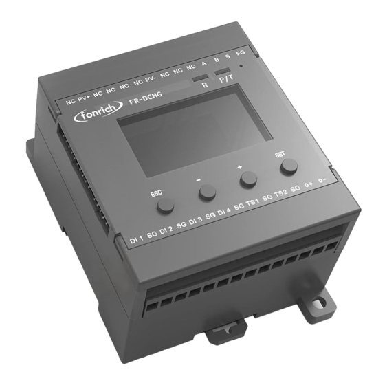
- Page 1 User Manual Version 1.1 DC System Monitor: FR-DCMG-MMPS 丰郅(上海)新能源科技有限公司 Fonrich (Shanghai) New Energy Technology Co., Ltd. Add: 1st Floor, Building 5, No.999 Jiangyue Road, Minhang District,Shanghai Web: www.fonrich.com Tel: +86 21 61679671 Email: sales@fonrich.com...
-
Page 2: Table Of Contents
Table of Contents Documentation statement ............................ 1 Product description ............................2 The main function ............................2 Optional module............................3 Terminal description ........................... 4 (Optional) PLC expansion module terminal description ................5 Ground connection and RS485 communication shielded wire ..............6 Wiring diagram of monitoring module ...................... - Page 3 Communication format configuration ....................19 Data frame format description (refer to Modbus RTU standard) ............19 Function code description ....................... 19 Register description ........................20 Register description in bit units (function code 02) ................20 Register description in word unit (function code 03 04 06) .............. 30 PLC register: ..............................
-
Page 4: Documentation Statement
Documentation statement This manual is applicable to the products with the models of FR-DCMG-MMPS. The software version is the monitoring module of version A088 and above; this document also contains the description of the optional product PLC. -
Page 5: Product Description
Display content: For the detected voltage, current, temperature, switching state, power • generation and other data, the FR-DCMG-MMPS can display a histogram interface through the LCD to read the current and other data more intuitively. Alarm function: It can be configured to open or close the alarm and shunt release functions •... -
Page 6: Optional Module
Optional module Type Model Description power line carrier(PLC) expansion module for Optional: expansion FR-DCMG-PLCD 1000V and below systems, needs to be used module with FR-DCMG-MMPL (PLC communication) FR-DCMG-PLCU For 1500V and below systems... -
Page 7: Terminal Description
Terminal Definition Symbol Meaning PV+ . PV- PV DC bus power supply terminal Not connecion Not connecion RS485 Communication terminal Fixed Ground terminal TS1.TS2 Externally connected temperature sensor terminals Temperature sensor and digital input ground terminal DI1.DI2.DI3.DI4 4 digital input terminals 0+.0- Connecting the shunt release Can connect modules with FUC interface... -
Page 8: (Optional) Plc Expansion Module Terminal Description
(Optional) PLC expansion module terminal description Symbol Meaning PLCx PV+ . PV- PLCx expansion module DC power terminal... -
Page 9: Ground Connection And Rs485 Communication Shielded Wire
Ground connection and RS485 communication shielded wire The FG terminal of the FR-DCMG must be grounded, otherwise communication will interfere and the reliability of the device will decrease. The grounding wire should be grounded nearby. The grounding wire should be no more than 15cm from the “FG” terminal to the bottom of the combiner box. It is recommended to be within 10cm. -
Page 10: Wiring Diagram Of Monitoring Module
Wiring diagram of monitoring module... -
Page 11: (Optional)Plc System Network Wiring Diagram
(Optional)PLC system network wiring diagram System diagram... -
Page 12: Network Diagram
Network diagram Networking diagram of the gateway in the inverter Networking diagram of the gateway in the junction box... -
Page 13: Plc Wiring In Combiner Box And Inverter
PLC wiring in combiner box and inverter... -
Page 14: Ui Introduction
UI introduction Key operation FR-DCMG-MMPS has four keys “ESC”, “-”, “+”, and “SET”. "ESC" key is used to return to the default interface and cancel parameter setting and View PLC status; “SET”key is used to enter the parameter setting mode, select the parameter to be set and complete the setting of the parameter;... -
Page 15: Plc Status Interface
⑥ Current histogram; the default display range is -2A ~ 10A, and the display range can be expanded by setting register 0x0B16; ⑦Histogram partition: because 6 Halls are inserted, 6 partitions PLC status interface In the histogram interface, without the PLC expansion module connected, press the ESC key to display the following interface: With the PLC expansion module connected, press the ESC key to display the following interface: Node mode... -
Page 16: Parameter Settings
first, and when the "-" is pressed first, the digital value of the current is displayed first The value of cumulative power generation. When viewing the values of current and cumulative power generation, you can scroll through the screen by continuing to press the "+" or "-" key. After the current display is completed, continue to press the "+"... -
Page 17: Trip Self-Test Setting Interface
MODE: PLC mode (Gate gateway, Node node, node address and Modbus address are the • same, setting range 1-24) BAND: PLC frequency band (currently only supports FCC, please consult technical staff for • other options) TEI: PLC's network identification (the TEI under the same network must be consistent, •... -
Page 18: Current Calibration Setting Interface
In the shunt trip setting interface, you can set the enable time (TIME) and trip self-check (SELFCHECK) of the shunt trip during the arc alarm. When "*" flashes in the TIME line, press the "SET" key and then press ± to modify the shunt release time. -
Page 19: Alarm Status Display Interface
Alarm status display interface Alarm messages can be cleared remotely and manually. Manual clearing requires long-pressing the host's "ESC" key for 2 seconds, remote clearing requires writing "1" to register 0x0079 to clear. If an arc trip alarm occurs, it must be cleared manually or remotely. Restarting the host will still display the alarm message. -
Page 20: Alarm Information Management
Alarm information management Items that can generate alarms can be set Channel arc Voltage is too high Voltage is too low Temperature is too high Channel reverse current Total reverse current is too high Total current is too high Total current is too low Channel without current Low channel current High channel current... -
Page 21: Alarm Message
Current reverse, no current, under current, over current, low current, high current, etc. Channel alarm and trip judgment preconditions: They need to meet their alarm conditions. At the same time, if the cumulative number of alarm channels is greater than the set number of trip channels, tripping will occur. -
Page 22: Modbus Protocol Definition
MODBUS Protocol Definition Communication format configuration Modbus communication mode: RTU mode • Address of the slave device: range form 1 to 247 (default 247) • Baud rate (bps): 2400, 4800, 9600 (default), 19200, 38400 • Byte check mode: odd check, even check, no check (default) •... -
Page 23: Register Description
Register description Register description in bit units (function code 02) Bit address Functional description remark Decimal 0x0200 Bus arc trip state The bus arc is faulted and a trip is performed and this bit is set. Clear the alarm and set it to 0. 0x0201 Channel arc trip state The channel arc is faulted and a trip is performed and this bit is set. - Page 24 .......... 0x021E Remote manual trip status The remote manual control release performs a trip action and this bit is set to 1. Clear alarm after setting 0 0x0230 Bus arc alarm status This bit is set when the bus arc strength is above the alarm threshold.
- Page 25 0x0261 Channel 2 arc alarm status When the arc intensity of the channel is greater than the alarm threshold, this bit is set to 1; after clearing the alarm, it is set to 0 0x0262 Channel 3 arc alarm status When the arc intensity of the channel is greater than the alarm threshold, this bit is set to 1;...
- Page 26 0x0277 Channel 24 arc alarm status When the arc intensity of the channel is greater than the alarm threshold, this bit is set to 1; after clearing the alarm, it is set to 0 ............0x0280 Channel 1 current reverse This bit is set when the channel current is reversed and greater than alarm status the alarm threshold, otherwise cleared.
- Page 27 0x0294 Channel 21 current reverse This bit is set when the channel current is reversed and greater than alarm status the alarm threshold, otherwise cleared. 0x0295 Channel 22 current reverse This bit is set when the channel current is reversed and greater than alarm status the alarm threshold, otherwise cleared.
- Page 28 0x02B1 Channel 18 no current alarm This bit is set to 1 when there is no current in this channel, otherwise status cleared. 0x02B2 Channel 19 no current alarm This bit is set to 1 when there is no current in this channel, otherwise status cleared.
- Page 29 0x02CE Channel 15 undercurrent This bit is set to 1 when the channel is undercurrent, otherwise alarm status cleared. 0x02CF Channel 16 undercurrent This bit is set to 1 when the channel is undercurrent, otherwise alarm status cleared. 0x02D0 Channel 17 undercurrent This bit is set to 1 when the channel is undercurrent, otherwise alarm status cleared.
- Page 30 0x02EB Channel 12 overcurrent This bit is set to 1 when the channel is overcurrent, otherwise alarm status cleared. 0x02EC Channel 13 overcurrent This bit is set to 1 when the channel is overcurrent, otherwise alarm status cleared. 0x02ED Channel 14 overcurrent This bit is set to 1 when the channel is overcurrent, otherwise alarm status cleared.
- Page 31 0x0308 Channel 9 current low alarm This bit is set to 1 when the channel current is too low, otherwise state cleared. 0x0309 Channel 10 current low This bit is set to 1 when the channel current is too low, otherwise alarm state cleared.
- Page 32 0x0325 Channel 6 current too high This bit is set to 1 when the channel current is too high, otherwise alarm state cleared. 0x0326 Channel 7 current too high This bit is set to 1 when the channel current is too high, otherwise alarm state cleared.
-
Page 33: Register Description In Word Unit (Function Code 03 04 06)
Register description in word unit (function code 03 04 06) Modbus address Function description Data Type instruction Decimal Address 0x0100 ~ 0x0158, a total of 89 consecutive addresses Address 0x0100 ~ 0x0123, a total of 36 consecutive addresses (data in this address supports data freeze) 0x0100 Retain 0x0101... - Page 34 bit13 channel current value is low bit14 channel current value is high 0: No alarm, 1: Alarm, default 0 0x012E Retain Channel 1 ~ 16 arc alarm 0x0130 Unsigned Default 0 short 0: No alarm, 1: Alarm 0x0131 Channel 17 ~ 24 arc alarm Unsigned Default 0 short...
- Page 35 generated energy of Channel short 0x024B The lower 16bit of the Unsigned Unit Wh, default 0 generated energy of Channel short Arc information (0x0250-0x0297) 0x0250 Channel 1~24 arc intensity short Unit 1, default 0 real-time value 0x0267 0x0268 Channel 1~24 arc intensity short Unit 1, default 0 history maximum...
- Page 36 threshold short undercurrent, overcurrent, no current, high current, and the number of channels with low current is greater than or equal to this value, the trip unit performs the tripping action. Otherwise it will not work. 0x0B0E 2830 Channel arc intensity super Short The default is 70.Need to set according to high alarm threshold...
- Page 37 bit7 Reverse total current is high, bit9 The total current is high, bit10 Channel current value is zero, bit11 Channel current value is undercurrent, bit12 Channel current value is overcurrent, bit13 The channel current value is low, bit14 The channel current value is high, 1: enable (open) alarm, 0: disable(close) alarm Default:0x0003...
- Page 38 0x0C92 3218 Broadcast time - minutes, Unsigned Keep to the next broadcast, high 8 digits: seconds short minute, low 8 digits: second 0x0C93 3219 Retain System settings (0xFE00-0xFE54) 0xFE00 65024 Modbus address Unsigned Set range 1 ~ 247, default 247. short Set other values to restore the default values.
- Page 39 number short 0xFE19 65049 PVP board hardware serial Unsigned System information (not open) number short 0xFE1A 65050 Modbus master time_ms Unsigned System information (not open) short 0xFE1B 65051 Almtrip time_ms Unsigned System information (not open) short 0xFE1C 65052 Power and kwh time_ms Unsigned System information (not open) short...
-
Page 40: Plc Register
PLC Register: Function code 03 Modbus address Function description instruction Decimal 0x3000 12290 Read current TEI 0-99 0x3001 12290 Read the number of packets currently sent 0x3002 12290 Read the current working mode 1: gateway mode, 0: node mode 0x3003 12291 Read the number of nodes online The value range is 0 ~ 16, the current number of online nodes 0x3004... - Page 41 0x3024 12324 Node11's tonemap (high 16 bits) 0x3025 12325 Node11's tonemap (low 16 bits) 0x3026 12326 Node12's tonemap (high 16 bits) 0x3027 12327 Node12's tonemap (low 16 bits) 0x3028 12328 Node13's tonemap (high 16 bits) 0x3029 12329 Node13's tonemap (low 16 bits) 0x302A 12330 Node14's tonemap (high 16 bits)
- Page 42 connection quality 12394 Connection quality of node 3 The range is 0--255, the larger the value, the better the 0x306A connection quality 12395 Connection quality of node 4 The range is 0--255, the larger the value, the better the 0x306B connection quality 12396 Connection quality of node 5...
- Page 43 0x3089 Number of packets received from 12425 node 10 0x308A Number of packets received from 12426 node 11 0x308B Number of packets received from 12427 node 12 0x308C Number of packets received from 12428 node 13 0x308D Number of packets received from 12429 node 14 0x308E...
- Page 44 0x4850 18512 Reserved 0x4900 18688 Read node 10 data 0x4950 18768 Reserved 0x4A00 18944 Read node 11 data 0x4A50 19024 Reserved 0x4B00 19200 Read node 12 data 0x4B50 19280 Reserved 0x4C00 19456 Read node 13 data 0x4C50 19536 Reserved 0x4D00 19712 Read node 14 data 0x4D50...
-
Page 45: Function Code 06
0x5550 21840 Reserved 0x5600 22016 Read node 23 data 0x5650 22096 Reserved 0x5700 22272 Read node 24 data 0x5750 22352 Reserved Function code 06 Modbus address Function description instruction Decimal 0x3000 12288 Setting up TEI 0-99 0x3002 12290 Set working mode Low byte is valid, 1: gateway mode, 0: node mode, others are invalid 0x3003... -
Page 46: The Data Of Plc Node 1 Is As Follows, The Data Of Other Nodes Are Similar
The data of PLC node 1 is as follows, the data of other nodes are similar: Modbus address Function Data Type instruction description Decimal 0x4000 16384 bus voltage Unsigned Unit V, default 0 Short 0x4001 16385 Temperature sensor 1 Short Unit: 0.1 °... - Page 47 bit6 channel current value reverse bit7 total reverse current is high, bit8 total current is low, bit9 total current is high, bit10 channel current value is zero, bit11 channel current value undercurrent bit12 channel current value overcurrent bit13 channel current value is low bit14 channel current value is high 0: no alarm, 1: alarm, default 0 0x402e...
-
Page 48: Appendix
Appendix Troubleshooting for screen flicker(Please refer to page 3 of the manual to deal with the problem of excessive interference from shielded wires)... -
Page 49: Document Revision Record
If you have any questions about this product, please contact us. Please remember the following contact information: Fonrich (Shanghai) New Energy Technology Co., Ltd. Add: 1st Floor, Building 5, No.999 Jiangyue Road, Minhang District,Shanghai Zip code: 201114 Tel :+86 21 61679672 sales@fonrich.com...
Need help?
Do you have a question about the FR-DCMG-MMPS and is the answer not in the manual?
Questions and answers