
Related Manuals for Alarko CARRIER ALM Series

Summary of Contents for Alarko CARRIER ALM Series
- Page 1 ALG SERIES GAS BURNERS ALG 50/2, ALG 70/2 INSTALLATION , OPERATION MAINTENANCE ALM SERIES LIGHT OIL BURNERS INSTALLATION / ASSEMBLY, OPERATION, MAINTENANCE...
- Page 2 Rev. No: 0 Book Revision Date: 140606 Book Edition Date:...
-
Page 3: Table Of Contents
CONTENTS INTRODUCTION............4 DECLARATION OF CONFORMITY. -
Page 4: Introduction
3 (three) years starting from the date of sale. The Certificate of Warranty must be filled out and forwarded to ALARKO CARRIER by the Dealer who sold you the burner. Please ensure that this Dealer has completed and sent off the Certificate... -
Page 5: Safety Precautions
It is suggested that the annual periodic maintenance of your burner as well as its commissioning be made at the beginning of each heating season by your Authorized dealer or an Alarko Carrier Service Engineer. -
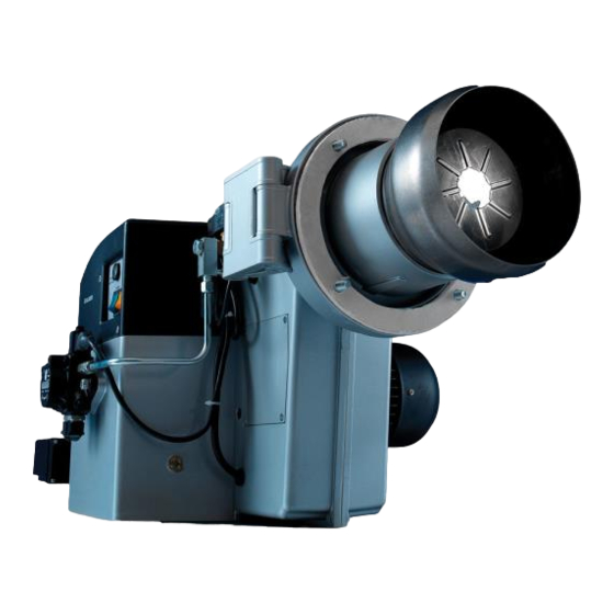
Page 6: Main Parts Of Burner
MAIN PARTS OF BURNER ALM 125\2, ALM 174\2 Burner Casing Control Unit Top Cover Fuse Boiler Connection Flange Cable Gland Boiler Connection Gasket Combustion Head Hinge Solenoid Valve Burner Motor Air Damper Motor Fuel Pump Sight Glass Nozzle Button Nozzle Button Photocell Solenoid Valve 10. -
Page 7: Principles Of Operation
PRINCIPLES OF OPERATION The ALM Series burners receive the air for combustion via the air suction chamber. After passing through this air suction chamber, the combustion air enters into the burner and reaches the combustion head mixing point via a fan operating in the volute shaped casing. The mixing point consists of the air diffuser and the combustion head. -
Page 8: Dimensions
DIMENSIONS (mm) BURNER Ø D Ø P Ø S TYPE min. max. min. max. ALM 125/2 986 1023 726 260 297 204 375 525 926 1007 895 976 152 300 R824 R756 230 45° ALM 174/2 996 1033 734 262 299 226 CONNECTION OF BURNER TO THE BOILER The front edge of the burner’s combustion head should exceed the boiler cover thickness by a minumum t value (t=10-14 cm), (See figure 1). - Page 9 The fixing plate (flange) (9) should be prepared according to the dimensions given in Figure 2. The boiler connection flange (4) may be used a template for the M10 holes. Figure 2 The top view of the burner is shown in Figure 3. In order to connect the burner to the boiler, remove the nut (1) first.
-
Page 10: Pushing Forward And Pulling Back
Fix the burner by pushing its diffuser group (10) through the boiler connection flange (4) Then loosely fix the nut (1) on the stud (8). (See figure 6). The hinge piece (2) on the burner is coupled with the hinge on the connection flange (4) by aligning with the hinge rod (3).Then nut (1) is tightened (See figure 7). -
Page 11: Electrode Adjustments
Following the connection to the boiler and the pushing forward and pulling back operations, the burner is pulled back from the nozzle holder onto which the nozzle is to be installed is reached. The plastic plug on the nozzle holder is removed and nozzles supplied accessories bag are fitted. -
Page 12: Combustion Head-Diffuser Adjustment
COMBUSTION HEAD-DIFFUSER ADJUSTMENT The combustion head and the diffuser must be properly adjusted in order to ensure efficient combustion. The adjustment values shown below represent average values obtained during testing to the EN 267 requirements. Depending on the different boiler room conditions, the combustion values attained by these adjustments may be improved. - Page 13 Select “Combustion Head-Diffuser Adjustment value” corresponding to the capacity value required. Combustion Head- Diffuser Adjustment Curve is also Based on Capacity. Remove the diffuser group (10) of burner (See figure Figure 13 13)from boiler (See figure 14) with the help of the hinges (2).
- Page 14 Measure the distance between diffuser disc and combustion head (See figure 17), after assembling the combustion head onto the diffuser group, this group removed with the help of hinges. In order to adjust the desired distance, move the combustion head (14) over to the combustion head connecting piece (13) and adjust its distance.
-
Page 15: Combustion Airflow Adjustment With Air Damper (Lks 160)
COMBUSTION AIRFLOW ADJUSTMENT BY DAMPER MOTOR The combustion air enters in the burner via air suction chamber. A flap in the air suction chamber adjusts this airflow. The air damper actuator in two stage burners operates this air flap. The system consists of a 1 stage airflow adjustment cam, stage airflow adjustment cam and 1 stage to 2... -
Page 16: Airflow Adjustment
COMBUSTION AIRFLOW ADJUSTMENT WITH AIR DAMPER (LKS 160) During operation of the burner, the first stage operation is performed with a reduced air supply. Any airflow adjustment should be made at the start of combustion airflow trial. Check the burner for correct operation at this time. The curves below show the air flap adjustment points as a function of boiler capacity. -
Page 17: Commissioning
COMMISSIONING Remove the electrics panel cover to allowing access to the power supply cables and boiler thermostat cables via the cable entry unions. Connect the cables as per the wiring diagram (see page 21 and 22). These connections are of split type, and will allow you to connect the phase leads to terminals L1, L2 and L3 and the ground lead to terminal N. -
Page 18: Oil Delivery
PUMP PRESSURE REGULATION A pressure gauge is connected at the connection point No. 5 for pressure monitoring. A vacuum gauge is connected at the connection point No. 3 for vacuum monitoring. Any bleeding operation must be performed during the burner operation until the fuel flows without any air bubbles being observed from the pressure gauge connection point when it is loosened slightly. - Page 19 One pipe siphon feed system Nozzle (US GPH) d (mm) H (m) E max. = 20m (E-H) max. = 4,5 m One pipe lift system Nozzle (US GPH) d (mm) H (m) H max. = 4,5 m Two pipe siphon feed system Pump AJ4/J4/E4 AJ6/J6/E6...
-
Page 20: Nozzle
NOZZLE The nozzle injects the fuel pumped under pressure by the pump into the combustion chamber. The fuel, upon striking to the air at a high speed pulverizes into very tiny particles, this is now capable of vaporizing and mixing with the air. 1 Tangential slots 2 Distributor 3 Valve Jacket... -
Page 21: Nozzle Selection
NOZZLE SELECTION For light oils (up to a viscosity value of 6 cSt at 20 C), nozzles supplied by Steinen, Monarch and Hago are best. The Steinen nozzles with a spray angle of 60 should be used. RECOMMENDED NOZZLES ACCORDING TO BURNER CAPACITY 3,4 ... -
Page 22: Control Unit Operation Program
CONTROL UNIT OPERATION PROGRAM The control unit is the most important element of control system. The control unit allows the operation of the burner in accordance with control signals provided by the control circuitry. The LM0 44 is an electro-magnetic unit. LM0 44 : CONTROL SEQUENCE, OPERATION AND TIMING Waiting time 5 sec. - Page 23 Color code table for multicolor signal lamp Status Color code Color Waiting time “tw”, other waiting statuses ....... Oil preheater on (if exist), waiting time “tw” n....... Yellow Ignition phase, ignition controlled Flashing yellow ....... Operation, flame o.k. Green Operation, flame not o.k.
-
Page 24: Wiring Diagram
WIRING DIAGRAM CONTROL UNIT Phase Neutral Motor Solenoid Valve Ignition Transformer ST : Safety Thermostat BT : Boiler Thermostat F : Fuse Failure IT : Ignition Transformer SV : Solenoid Valve Photocell C1 : Contactor T1 : Thermal Relay Control Unit : LMO24 255B2 or LMO44 255B2 may be used Burner Nozzle-2... -
Page 25: Maintenance
MAINTENANCE All adjustments of the burner may be easily made in that part of the burner. This is because the burner can be taken out of the boiler with the help of the hinge system. It can then be re-assembled back into the boiler and fixed (See figure 1). - Page 26 Figure 5 Figure 6 The control unit, contactor, fuse and the LED button may easily be reached (See figure 5) by removing three M5 bolts on the electric panel cover (See figure 6).
-
Page 27: General Maintenance Rules
GENERAL MAINTENANCE RULES •Keep the boiler room clean. •Clean the filters on the fuel line every week with clean light oil. •Clean the pump filter at least once every year. •Remove any particles of soot etc. which may accumulate in the slots of the diffuser disc. -
Page 28: Problem /Possible Cause / Solution
PROBLEM /POSSIBLE CAUSE / SOLUTION PROBLEM POSSIBLE CAUSE SOLUTION Burner doesn’t a) Lack of contact in the boiler thermostat a) Check operate. connections. b) Fuse may be blown. b) Check c) Discontinuity in grounding. c) Check d) No power supply to the burner.* d) Check e) Boiler thermostat is not properly adjusted* e) Readjust... - Page 29 PROBLEM /POSSIBLE CAUSE / SOLUTION PROBLEM POSSIBLE CAUSE SOLUTION Nozzle failures a)Nozzle is dirty. The formation of flame sparks and a)Clean smoke is observed. The formation of a complete flame cone is observed. b)Inner cone of nozzle is damaged. b)Replace c)Loose nozzle.
Need help?
Do you have a question about the CARRIER ALM Series and is the answer not in the manual?
Questions and answers