Advertisement
Quick Links
Applied Machines: C368/C308/C258/PRO958/958/808/758
COLOR MFP: 36 ppm/30 ppm/25 ppm
MFP: 95 ppm/80 ppm/75 ppm
Product Code: A7PU/A7PY/A7R0/A796/A8KN/A795
1. Accessory parts
No.
Name
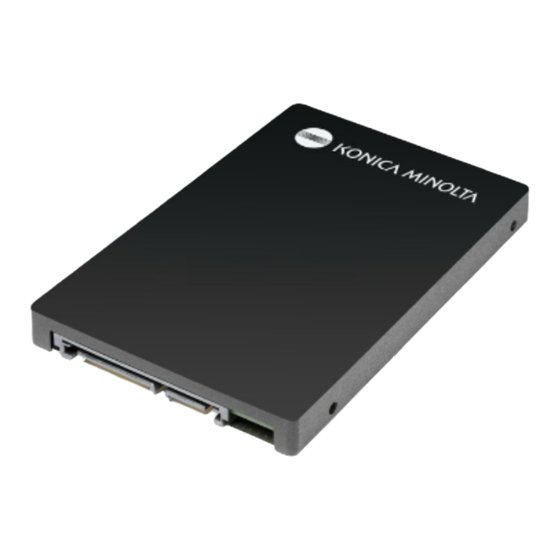
1. Hard disk
2. Cable A
3. Cable B
4. Ferrite core
*1*2
5. Screw
(3 x 8 mm)
6. Installation
manual
*1
The parts is not used in North America.
*2
Used only when this option is installed to the
models C368/C308/C258.
HD-524
INSTALLATION MANUAL
Shape
Q'ty
1
1
1
1
4
1
set
Hard Disk
Keep this bag away from babies and
children. Do not use in cribs, beds,
carriages, or playpens.
The thin film may cling to nose and
mouth and prevent breathing. This bag is
not a toy.
Note:
• The hard disk is highly susceptible to impact.
Handle it with utmost care not to drop it or hit it
against any object. Do not touch the board sur-
face and pins.
• This manual provides the illustrations of the
accessory parts and machine that may be
slightly different in shape from yours. In that
case, instead of the illustrations, use the
appearance of your machine to follow the
installation procedure. This does not cause any
significant change or problem with the proce-
dure.
E-1
A888-9551-01
Advertisement

Related Manuals for Konica Minolta HD-524


Summary of Contents for Konica Minolta HD-524
- Page 1 HD-524 Hard Disk INSTALLATION MANUAL Applied Machines: C368/C308/C258/PRO958/958/808/758 COLOR MFP: 36 ppm/30 ppm/25 ppm MFP: 95 ppm/80 ppm/75 ppm Product Code: A7PU/A7PY/A7R0/A796/A8KN/A795 1. Accessory parts Name Shape Q’ty 1. Hard disk Keep this bag away from babies and children. Do not use in cribs, beds, carriages, or playpens.
-
Page 2: Installation Procedures
2. Installation procedures (4) Remove the lower rear cover. (11 screws) <Installations to models C368/C308/C258> Follow the installation procedures starting on page E-2. <Installations to models PRO958/958/808/758> Follow the installation procedures starting on page E-4. <Installations to models C368/C308/C258> (1) Turn OFF the power switch and unplug the power cord from the power outlet. - Page 3 (9) Connect the cables installed in step (6) to the <Only when installing in the marketing areas other machine. than North America> Note: Attach the supplied ferrite core to the cable A as Ensure that the cables A and B do not contact with shown in the illustration.
- Page 4 <Installations to models PRO958/958/808/758> (11) <Only when the sheet is removed in step (5)> (1) Turn OFF the power switch and unplug the Tighten the three screws removed in step (5) at power cord from the power outlet. the positions shown in the illustration. (2) Remove the six caps of the upper left rear cover.
- Page 5 (5) Remove the cap of the upper right rear cover (8) Attach the hard disk to the main body. (Four sup- and the filter. plied screws) Note: Hook the two claws of the hard disk at the posi- Filter tions shown in the illustration. (6) Remove the upper right rear cover.
-
Page 6: Configuration Procedures
3. Configuration procedures (10) Place the cables A and B in the edge cover. Note: <HDD mirroring rebuilding> When installing the upper left rear cover, place the (1) Plug the power cord into the power outlet and cables into the cover so that they do not touch the turn ON the power switch.
Need help?
Do you have a question about the HD-524 and is the answer not in the manual?
Questions and answers