
Related Manuals for MBM FC 10 PLUS

Summary of Contents for MBM FC 10 PLUS
- Page 1 SERVICE MANUAL MBM TABLETOP COLLATOR MODEL FC 10 PLUS R e v 1 . 0 Sep .09.2016 - 0 -...
-
Page 2: Table Of Contents
CONTENTS Components ........................... 4 Overview ......................... 4 Operation Panel ....................... 6 Precaution for Maintenance and Inspection .................. 8 Usual maintenance ......................8 2.1.1 Clean-up paper feed roller, separator and Paper Ejection sheet photo sensor ..8 2.1.2 Cleaning of Paper Ejection sheet photo sensor .......... - Page 3 Back door ........................27 9.2.1 Dismounting procedures of the back door ............27 9.2.2 Remove flat belt ....................28 Anti-operation side ....................... 30 9.3.1 Optical sensor for encoder .................. 30 9.3.2 Paper feed clutch ....................30 9.3.3 Timing belt ......................33 9.3.4 Breaker .......................
- Page 4 Troubleshooting ......................... 63 13.1 The power is not supplied ..................63 13.2 .... 63 Paper is not fed through the CHECK key is pressed (Main motor does not rotate) 13.3 Paper is not fed though the CHECK key is pressed (Main motor rotates) ....
-
Page 5: Components
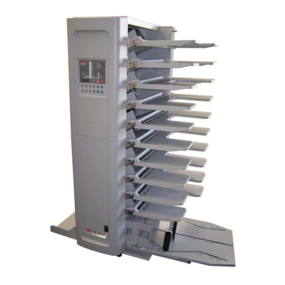
COMPONENTS 1.1 Overview... - Page 6 Name Name Left cover Shift lever for paper direction Operation Panel Back door Paper guide Paper feed roller Paper feed table Stacking side guide Power switch Aligning wire Plate to prevent the machine from falling (rear) Stacking pole Stacking end guide Plate to prevent the machine from falling (front) Stacking table Circuit breaker...
-
Page 7: Operation Panel
Operation Panel... - Page 8 Name Function Shows the collating status of each station 1 through 10 Station Green lamp Flashes red in the event of jam or double feed. Station Red lamp Lights up when the back door is open. DOOR lamp Shows direction of paper ejection when lighted green. Indicates an error in the left side option when lighted red.
-
Page 9: Precaution For Maintenance And Inspection
2. PRECAUTION FOR MAINTENANCE AND INSPECTION - Before starting maintenance and inspection work, be sure to turn the power off and remove the power cord from the outlet. - Photo sensors are used in various parts of this machine. Be sure to clean them when maintenance work is conducted. - Page 10 (1) Remove the paper feed tables and support tables. While holding the paper feed shaft, push it in to the left, then pull it toward the front. (2) After removing the paper feed shaft, clean its three rubber rollers. (3) Draw out the separator in the direction of the white arrow shown in the figure below, and clean the rubber portion.
-
Page 11: Cleaning Of Paper Ejection Sheet Photo Sensor
2.1.2 Cleaning of Paper Ejection sheet photo sensor When the paper dust adheres to the surface of the Paper Ejection photo sensor (contained in the part indicated by the arrow shown in the figure below) and will shut off the sensor light, it becomes paper discharge jam. -
Page 12: Preparation For Use
PREPARATION FOR USE 3.1 Installing attachments 3.1.1 Mount the plate to prevent the machine from falling (1) Insert the front fall prevention plate under the body of the collator and fix the plate with four attached screws. (indicated by the white arrow) Front fall prevention plate (2) Mount the rear fall prevention plate, and fix the plate... -
Page 13: Stacking Table Assembly
3.1.3 Stacking table assembly (1) Insert the 2 stacking side guides and the stacking end guide in the stacking table, making sure not to set them in the wrong direction. (2) Insert the 2 stacking poles in the holes and fix them while sliding them along the slot. -
Page 14: Switch Single/Option
Remarks a) Make sure the stacking table and aligning wire are properly attached to the machine; wrong attachment may cause the machine to rock or paper to jam when ejected. b) Take care so that fingers or hands are not caught in collator operating parts. -
Page 15: Display Of Total Count Of Sheets
3.1.6 Display of total count of sheets The total count of sheets from the date of purchase can be displayed by following the steps described below. (1) Press the “SET” key to switch the mode to Set (the SET indicator lamp will come on). (2) Hold down the “9”... -
Page 16: Setting Paper
4. SETTING PAPER 4.1 Precautions for setting paper (1) Use the fill line on the paper guide as the loading capacity. In case of printed paper, do not load too much as it tends to swell. (2) Fan out sheets well and then load them on the feed table. Failure to properly fan sheets may lead to trouble. -
Page 17: Order Of Loading Paper
4.2 Order of loading paper (1) Paper with the printed side down Load the paper on the feed tables from bottom to top in ascending order of pages. In this case Page 1 appears at the top of collated sheets on the stacking table. -
Page 18: Loading Paper In Insert And Program Mode
4.4 Loading paper in Insert and Program mode (1) Insert mode Load partitioning paper on the top station to be used. For instance, if 10 stations are used continuously top to bottom, partitioning paper should be loaded on Station 1. (2) Program mode Be sure to load paper with the printed side up. -
Page 19: Response To Light And Flashing Of Lamps (Error Message)
5. RESPONSE TO LIGHT AND FLASHING LAMPS (ERROR MESSAGE) Counter Other display Possible cause Action display CHECK lamp and the They light when checking is relevant station lamp light Use the machine as they are. completed. green Station lamp lights red. EJECT lamp and the Paper remains in the paper feed Remove the paper shielding the... -
Page 21: Main Printed Circuit Board
6. MAIN PRINTED CIRCUIT BOARD... -
Page 22: Wiring Diagram
Wiring Diagram... -
Page 23: Paper Detection Wire Angle Adjustment Procedures
wire angle adjustment procedures Paper detection Dismount the cover on the operating side Unscrew the screws on the sheet metal frame and open it Lowering the paper feed table, loose the Philips screws of the paper detection up-lever, and move to the right and left sides to make it free When the paper detection up-lever is moved to the right side, the paper inspection wire will move to the upper side by the paper detection lever. -
Page 24: How To Replacement Of Parts
9. How to replacement of Parts Operation panel side Remove the decorative cover on the operation panel side. Unscrew total 10 of screws at the right and left sides of the cover. 9.1.1 Power switch Note: There are 4 wires to the power switch, and the 2 front side wires of them are white and the 2 back side wires are black. - Page 25 Draw out the Faston terminals with a needle nose plier. As shown in the photo, grab a Faston terminal with a needle-nose plier, and push the thumb for smooth drawing out. Pushing the projected portions at the upper and lower sides of the power switch, remove the power switch.
-
Page 26: Long Distance Transmission Sensor (Receiving)
9.1.2 Long distance transmission sensor (Receiving). (As for the emission side, see 8.3.5) Unscrew the fixing screws to exchange the long distance transmission sensor. 9.1.3 Paper Ejection sheet switching micro switch Unscrew the 2 fixing screws to exchange the Paper Ejection sheet switching micro switch. Caution: Wire up to the position of “normally closed”... -
Page 27: Door Open Detection Micro Switch
9.1.5 Door open detection micro switch Unscrew the 2 fixing screws. Open the back door and the mounting plate for the operating panel. Unscrew the 2 fixing screws. -
Page 28: Back Door
Dismount the door switch holder. Unscrew the 2 fixing screws to exchange the door open detection micro switch. Caution: Wire up to the position of “normally closed” as described above. Back door 9.2.1 Dismounting procedures of the back door Open the back door and pull down the latch at the upper portion to dismount the back door. -
Page 29: Remove Flat Belt
9.2.2 Remove flat belt (Upper) Unscrew the 4 fixing screws. (Lower) Unscrew the 4 fixing screws. Unscrew the M3 cap screws with a hexagonal wrench. Unscrew the M3 cap screws at the opposite side in the same manner. - Page 30 Remove door tension spring. Unscrew bind-head screw 4 x 45. When the crown roller at the far end is removed, The status where the belt is removed: the flat belt can be removed.
-
Page 31: Anti-Operation Side
Anti-operating sides 9.3.1 Optical sensor for encoder Unscrew the 2 fixing screws to exchange the optical sensor for encoder. 9.3.2 Paper feed clutch Dismount the paper-feed table and the paper-feed roller shaft from the station to exchange the paper-feed clutch. - Page 32 The paper-feed clutches for 2 stations are fastened with one clutch holder. Cut-off the insulation lock for the clutch holder where the paper-feed clutches to be exchanged are fastened, and draw the connectors out. Dismount E-Rings (2 pieces). Unscrew the 2 fixing screws.
- Page 33 Dismount the clutch holder. Dismount the paper-feed clutch.
-
Page 34: Timing Belt
9.3.3 Timing belt Dismount the belt tension spring. Unscrew the 3 fixing screws. Dismount the paper ejection pulley holder. - Page 35 Lift up the flat idler pulley and slip off the timing belt.
-
Page 36: Breaker
9.3.4 Breaker Two breakers are used. Dismount the breaker at the paper ejection side after unscrewing the fixing screws. 9.3.5 Long distance transmission sensor (Send) Unscrew the fixing pan head screw with spring and plain washer. As for the receiving side, see 8.1.2. -
Page 37: Lift Motor
9.3.6 Lift motor Unscrew the 3 fixing screws. Loosen the 2 set screws (4x6) with a hexagonal wrench. (Don’t dismount) *Caution One of the two set screws, tighten D-cut surface of the lift motor. Unscrew the 4 fixing screws. -
Page 38: Main Motor
Remove the solder at 2 wires. (red and brown) * Solder the red and brown wires to the correct positions. Solder the red wire to the “+” terminal of the motor. 9.3.7 Main motor Unscrew the 6 fixing screws. Caution: Do not unscrew the fixing screws that fasten the sectioning motor. - Page 39 Cut-off the 3 insulation locks. Draw out the connector. Lift down the flat idler pulley and slip off the timing belt.
- Page 40 Unscrew the 4 fixing M4x8 pan head screw with spring and plain washer. Loosen the 2 set screws (4x6) with a hexagonal wrench. Draw out the Motor pulley. Unscrew the 2 fixing M4x20 pan head screws with spring and plain washer.
- Page 41 When mount the Main motor, adjust height two washers. Mount the motor pulley so that the encoder positioned in the center of the U-shaped encoder sensor, and fasten the setscrews.
-
Page 42: Body Case
Body case 9.4.1 Shift motor Pull out the connector. Unscrew the 6 fixing screws. Caution: Do not unscrew the fixing screws that fasten the sectioning motor. The sectioning motor will fall off when the screws are unfastened. If you attempt to run the motor in an unfixed state, it will malfunction. - Page 43 Loosen the two Set screws (4x6) with a hexagonal wrench. Caution: At assembly, fasten a set screw at the D-cut portion on the output shaft of the motor. Unscrew the 2 fixing screws. Unscrew the 3 fixing screws. Dismount the Shift motor.
-
Page 44: Micro Switch For Shift Motor
9.4.2 Micro switch for Shift motor Unscrew the 2 fixing screws. Dismount the micro switch. Caution: Wire up to the position of “normally closed” as described above. 9.4.3 Switching power supply Remove the unit in accordance with the procedure described in “8.4.1 Sectioning motor.”... - Page 45 Removal of 4 pan head screws with spring and plain washer will cut off switching power supply. screw, screwdriver through the hole of the ferrite core.
-
Page 46: Paper Ejection Roller (Upper)
9.4.4 Paper ejection roller (upper) When 2 pan head screws with spring plain unscrewed, the upper roller assembly for paper ejection will come off. When a paper ejection roller is provided At re-assembly, pay attention on the positions of the springs and the mylar sheet. -
Page 47: Paper Ejection Roller(Lower)
9.4.5 Paper ejection roller(lower) Dismount the paper ejection roller (upper). (Refer to section 8.4.4.) Unscrew the 5 fixing screws. Paper ejection roller (lower) Unscrew the fixing screw for combine Paper ejection roller (lower) and Ejection gear. (White plastic) Paper ejection roller holder Dismount the Paper ejection roller holder and the paper ejection roller (lower). -
Page 48: Paper Feed Unit
Paper feed unit 9.5.1 Receiving board / Emission board Unscrew the 2 fixing screws. Dismount the guide-bottom. Dismount the parts at the both sides. (see Fig. below) Those are fastened by screws at the operating and the non-operating sides. - Page 49 In the same manner, dismount the upper and lower parts of the sensor to be exchanged. Dismount the paper feed table and feed roller shaft. Unscrew the 2 fixing screws.
- Page 50 Lift up the lower portion of the guide and unscrew the screws at the lower guide table. Unscrew the set screw (4x6) on the paper detection wire shaft. When the above set screw (4x6) is unscrewed, the paper detection wire shaft will come off.
- Page 51 Draw out the connector on the printed circuit board from the back door side. Take out the E-rings that fix the feed roller shaft. Caution: Be careful not to drop the bearings. While drawing paper-feed roller, take off the guide-top.
- Page 52 Exchange Receiving board and the emission board after dismounting of the two screws on each board. Caution: Depending on the Receiving stations to be exchanged, the clutch holders mounting panels for boards Emission required dismounted.
-
Page 53: Paper Detection Wire
9.5.2 Paper detection wire Unscrew the set screw (4x6) on the paper detection wire shaft. Dismount the paper detection wire shaft to exchange paper detection wire. To fix the paper detection wire, put one drop of instant adhesive on the wire and match the salient of the wire with the hole on the shaft. - Page 54 assemble paper detection shaft, set a set screw (4x6) at D-cut portion of the shaft. Positional relation D cut and Paper detection wire.
-
Page 55: Feed Roller
9.5.3 Feed roller Push the paper feed shaft assembly to the left side to take it off. Dismount paper-feed roller only from paper-feed shaft assembly and exchange it. Caution: Mount the rollers at the positions at which the white dots of the three rollers will turn to the right. -
Page 56: Diagram For Belt Installation
10. DIAGRAM FOR BELT INSTALLATION... -
Page 57: Test Mode
TEST MODE 11.1 How to set test mode Test mode is aimed at checking various machine functions individually. (1) Turn the power on while pressing both of RESET and CHECK keys . (2) The counter displays [C–]. (The test mode is ready.) 11.2 Test mode functions While the test mode is on, the following six modes can be selected by pressing the MODE key. -
Page 58: Checking The Operation
11.3 Checking the operation Key operation Function Display Remarks Switching only Changeover between high and SPEED lamp lights indication: Run the main SPEED/3 low speeds /lights out motor by pressing the “RESET” key. Each time “SHIFT /5” The status of the Origin key is pressed, the sorter SHIFT/5 shift operation... -
Page 59: Check On Sensor Function
11.4 Check on sensor function Lamp Function Remarks Station 1 to 10 Status of paper switch at each The lamp of the station where paper is loaded lights. (Green lamp) station Station 1 to 10 Status of paper feed photo The lamp of the station where paper jam occurs lights. -
Page 60: Changing The System Parameter
Key operation Function Increase the number of station by one 4 or 7 Reduce the number of station by one MODE CHECK Return to the CHECK mode of the main functions. RESET START Can’t Adjustment of the paper feed photo luminescence intensity 12. - Page 61 List of system parameter Initial Input Function Contents Item value range Not used Double feed Numeric If the setting is changed, the double 0 255 Threshold level feed detection function will not properly operate. Double feed detection 1,2,3key 0 or 1 Refer section 11.2 ON/OFF Setting of waiting time until next...
- Page 62 Numeric 0 999 Not used Numeric Paper feed time lag 0 999 Not used Not used The time limit will decrease when the Numeric setting is decreased, or will increase 0 999 Minimum feed gap when the setting is increased. A short time limit will result in inaccurate alignment of ejected sheets.
-
Page 63: Releasing Double Feed Detecting Function
12.2 Releasing double feed detecting function In case double feed cannot be detected since paper used is too thick or variations in print, collation can be continued by canceling double feed detection function. (1) Press [0] key for three seconds ( [ P x ] will be displayed). (2) Press the [MODE] key to display [A xxx] ( xxx represents the current set value). -
Page 64: Troubleshooting
TROUBLESHOOTING 13.1 The power is not supplied. Power plug is disengaged. Insert the plug in the outlet. Circuit breaker is tripped. Remove the cause and reset the breaker. Checking of outside conditions Rated voltage cannot be obtained at the outlet. Use another outlet. -
Page 65: Paper Is Not Fed Though The Check Key Is Pressed (Main Motor Rotates)
13.3 Paper is not fed though the CHECK key is pressed (Main motor rotates). The station lamp lights green when the paper Adjust the paper switch. feed table is raised with no paper loaded. Check the working The paper feed clutch does not work when the Refer to “12.8 Paper feed clutch does not status while setting START key is pressed. -
Page 66: Paper Feed Table Does Not Rise
13.6 Paper feed table does not rise. Check external Back door is open. Close the back door. conditions. Check while the TEST Paper feed table works while the CHECK Check the back door, paper ejection, paper mode is set. key is set. stacking full or paper feed photo sensor. -
Page 67: Paper Feed Roller Does Not Rotate
13.8 Paper feed roller does not rotate. Back door is open. Close the back door. Check external conditions. Paper feed shaft assembly is not set Set the paper feed shaft assembly properly. firmly at the main body. Check the status while Paper feed clutch works when the Refer to “12.3 Paper is not fed though the the TEST mode is set. -
Page 68: Stacker Does Not Work
13.9 Stacker does not work. Back door is open. Close the back door. Check external SWING/5 lamp is not lit. Set the SWING mode ON. conditions It works if stacking table is removed. Set the stacking table properly. DC24V cannot be detected between pins 1 and 3 of the operation circuit board The switching power supply is faulty. -
Page 69: Station Lamp Lights Red
13.11 Station lamp lights red. Slip of paper, etc. is caught in the paper feed Remove the paper. photo. Check exterior conditions Photo-sensor is stained with paper dust. Clean the paper feed photo. Check the paper feed sensor harness. Do not emit paper feed sensor. Check the paper feed photo harness. -
Page 70: Double Feed Frequently Occurs
13.13 Double feed frequently occurs. Sheets are not neatly set on the paper feed Arrange the sheets neatly. table. Printed sheets stick to each other. Reset them after loosening. Ink on the paper is not sufficiently dried. Use the paper after it is sufficiently dried. Too many sheets are loaded. -
Page 71: Empty Feed Or Jam Frequently Occurs
13.15 Empty feed or jam frequently occurs. Sheets are not neatly set on the paper feed Arrange the sheets neatly. table. Use the paper after the printing is sufficiently Printing on the paper is not sufficiently dried. dried. Paper not specified in the specifications is Use paper specified in the specifications. -
Page 72: Double Feed Lamp Lights Though A Single Sheet Is Fed
13.17 Double feed lamp lights though a single sheet is fed. Try to check again. Differently printed sheets are mixed in a Use the sheets of same quality in the same one certain station. station. Sheets printed by different machines are Set the same printed sheet based on the same mixed in a certain station. -
Page 73: Stacked Paper Is Not Neatly Aligned
13.19 Stacked paper is not neatly aligned. Guides and sheet stopper of the stacking table Set guides and sheet stopper to fit the paper are not set to fit the paper size. size. Sheets are not neatly set on the paper feed Align the paper and set the paper feed guide table. -
Page 74: Product Specifications
14. Product specifications 14.1 Specifications Stations(bins) 10 stations(bins) Paper Feed Roller separator system Station(bin) Capacity 350sheets of 17-lb bond (64g/ ) paper] 1.1"[approx. Paper Transport Belt roller system Stacking Capacity 2.6" approx. 880 sheets of 17-lb bond (64g/ ) paper] Paper Stacking System Right and left index system (20°...
Need help?
Do you have a question about the FC 10 PLUS and is the answer not in the manual?
Questions and answers