Advertisement
Quick Links
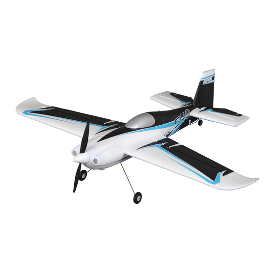
30% Edge 540 Instruction Manual
Congratulations, and thank you for choosing BME Aircraft ARFs.
Before you start your assembling, we'd like you to pay attention to this
step by step instruction manual, to ensure best performance.
I. Before assembling
2x main wheel
2x wing tube (large, small)
BME Aircraft
1. Parts check list ---
When you open your boxes of
30% Edge 540, check all the
parts. They should include the
followings:
1x fuselage
1x clear canopy 1x vertical fin
1x rudder
2x wheel pant
2x main wing (left, right)
2x aileron (left, right)
2x stabilizer (left, right)
2x elevator (left, right)
1x landing gear
1x tail wheel assembling
1x hardware pack
1
1x front hatch
1x cowl
Advertisement

Related Manuals for BME Aircraft Edge 540


Summary of Contents for BME Aircraft Edge 540
- Page 1 BME Aircraft 30% Edge 540 Instruction Manual Congratulations, and thank you for choosing BME Aircraft ARFs. Before you start your assembling, we’d like you to pay attention to this step by step instruction manual, to ensure best performance. I. Before assembling 1.
- Page 2 2. Iron all covered area Before you start your assembling. Iron all film covered area to ensure all color trim stick on firmly. 3. Cut out all covered holes Cut out all film covered holes for servos, hinges, wing tubes etc. II.
- Page 3 then draw a line around the tube. Insert the tube into the socket in the fuse and align the center line of both tube and socket. c. Drill and tap (6-32 rec.) the center through the spruce and tube. Use washer and spring washer on the bolt to secure the tube in place.
- Page 4 3. Rudder installation Install the control horn you choose to use on the hard point on the rudder. And glue the hinges (included) in place using 30min epoxy. Then glue all hinges into vertical fin with 30 min. epoxy. 4. Install tail wheel assembly Install tail wheel assembly as pictures shown below.
- Page 5 5. Canopy and front hatch a. Place canopy on top of the front hatch, make sure it’s centered and symmetrical on both side. Then draw a line along the edge of the canopy. b. Drill 3-4 holes on both side of canopy frame. Chose the same size drill bit as the wood screw you plan to use.
- Page 6 line according to the length from prop hub to the mounting plate, so that you can have a proper right thrust ( 3degree rec.) angle. The thrust line is located 2 3/4” from the bottom of the engine mounting box. b.
- Page 7 d. Place the spinner back plate into the shaft of the engine, CA glue the balsa onto the cowl and align the circle. e. Tighten a prop in front of the spinner plate, and align the cowl curve with the fuselage. Then mark the hole through the paper card strips.
- Page 8 d. Drill holes for 4-40 size screws according to the marks, secure the cowl with the screws provided. Cut off balsa donut in between spinner plate and cowl. B. Wings and Stabilizer 1. Place the fuselage inverted on a flat surface , then plug-in wings into the tube on both side.
- Page 9 4.Repeat the above step to complete the stabs. 5. Install control horns to the hard point on ailerons and elevators. Make sure that the push rods should be square to the hinge line when linked with servo arms. 6. Once the control horns are installed, next step is to hinge all control surfaces.
- Page 10 them into the holes. Do the same to the other side of the hinges and wings and complete installation of all hinges. C. Landing Gear and Wheel pants 1. Fasten wheel axles (provided) to the landing gear. Then secure wheel on the axle using two collars, one on each side of the wheel.
- Page 11 3. Mark and drill holes for the wheel pant holding bolts. Install T-nuts on the inside of wheel pants. Secure wheel pants with provided 4-40 screws. 4. Install landing gear on the designated location with provided 8-32 screws. Make sure you use both washers and spring washers.
- Page 12 Edge 540 should be located between 4.5” and 5.5” back from the leading edge of main wing. The incidence of the main wing, stab should be 0 degree as well as the engine thrust. Incidence should be checked when thrust line is leveled.
Need help?
Do you have a question about the Edge 540 and is the answer not in the manual?
Questions and answers