Advertisement
Quick Links
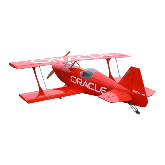
Congratulations and thank you for choosing BME Aircraft 27 % Pitts
Special Challenger. Before you start assembling, please pay attention to
this step by step instruction manual and follow the steps when
assembling.
I.
Before assembling
BME Aircraft
27% Pitts Special Challenger
1. Parts check list--
When you open your box of 27 %
Challenger, check all parts inside.
They should include as following:
1x fuselage
2 sets of main wings with ailerons
1 set of stabilizer and 2 elevators
1 set of fin and rudder
2x wing joiners
1x upper wing centre joiner
1
1x cowl
1x fuse belly
Advertisement

Related Manuals for BME Aircraft PAU Pitts


Summary of Contents for BME Aircraft PAU Pitts
- Page 1 BME Aircraft 27% Pitts Special Challenger Congratulations and thank you for choosing BME Aircraft 27 % Pitts Special Challenger. Before you start assembling, please pay attention to this step by step instruction manual and follow the steps when assembling. Before assembling 1.
- Page 2 1 set of tail wheel assembly 1 set of nylon sticker (3x ORACLE 1x landing gear and block 2x BME Aircraft) 1 set (4x) center cabane 2. Iron all film cover area--- Before you start assembling, Iron all film covered area to make sure that the film stick on firmly.
- Page 3 2. Fire wall installation— a. The fire wall in this ARF come unglued for easy access to install cabane. After the cabane installation, it’s time to install fire wall. First try fitting the fire wall into the engine box. Trim the fire wall if necessary.
- Page 4 balsa tri-block on the corner of the fire wall and box side wall. Install the gas tank before the fire wall is glued on. d. Drill and install dowels from the box side wall into the fire wall. e. The length from fire wall to the front surface of prop hub should be 5 3/4”.
- Page 5 f. Install landing gear onto the mounting plate using the provided screws. g. Cover landing gear with the balsa block. And secure the block with provided screws.. 4. Canopy— a. Try fitting the canopy in place. Draw a line along the edge of the canopy.
- Page 6 c. Apply the measurement to the stab symmetrically along the center line on both side. d. Cut out the covering along 2mm of the inner side of the line you just drawn on both side of the stab. e. Screw on the lower wing then insert the stab.
- Page 7 b. Screw the aluminum plate on the rudder as shown. c. Hook up the spring on both side. 7. Install cowl--- a. Prepare 6 strips of the paper card (1” x 5”). Drill a hole that a 4-40 size screw can go through. b.
- Page 8 the cowl and spinner back plate. e. Place a prop into the shaft and tighten it up. Mark and drill holes through the holes on the paper strip. f. Screw the cowl in place with 4-40 screws, then cut out the balsa donut.
- Page 9 2. Wing belly— Now find the lower wing fastening bolts from your hardware pack. secure lower wing underneath the fuse. Try fitting the belly piece in place. Draw a line along the side of the belly. Then cut out the covering film 2mm inside the line.
- Page 10 b. Lift up the tail and measure the incidence of the stab until it shows 0 degree. Hold the tail in that position with anything you can use. Then measure the incidence of the lower wing, it should also shows 0 degree.
- Page 11 1 1/2” in front of the LE. b. The recommended control surface throw is as follow: aileron 35 degree elevator 40 degree rudder 45 degree You are now ready to test fly your Pitts Special Challenger. Thanks again for choosing BME Aircraft. Enjoy your flying.
Need help?
Do you have a question about the PAU Pitts and is the answer not in the manual?
Questions and answers