Table of Contents
Advertisement
Available languages
Available languages
Quick Links
Advertisement
Table of Contents

Related Manuals for Radio Zeeland DMP Falcon F-701

Summary of Contents for Radio Zeeland DMP Falcon F-701
- Page 1 09 November 2010 Rev: 01 All information, pictures, drawings and technical schematics are the property of Radio Zeeland DMP. Unauthorized copying is prohibited. The content of this manual is subject to change without prior notice.
- Page 2 Version Date author Description 13-09-2010 Version 00 09-11-2010 Cable length added Waarschuwing: Dit product werkt op een elektrische spanning, voor uw eigen veiligheid adviseren wij het product nimmer te openen. Wanneer het product niet meer naar behoren functioneert dient u ten allen tijden het product ter reparatie aan te bieden bij een erkende dealer.
-
Page 3: Falcon F-701
EN 60945 (IEC 945 Third edition: 1996-11) Chapters 9, 10, 11 and 12. This declaration is issued according to the European Community Directive on Electromagnetic Compatibility (89/336/EEC). On behalf of Radio Zeeland DMP B.V. Terneuzen, the Netherlands Technical Manager 09-02-2010... - Page 4 Version: Date: 9 November 2010 Document: Falcon701 Ver01 Page 4 of 34 First release: 04 February 2010...
-
Page 5: Table Of Contents
3.2.5. Externe speaker uitgang ..................17 3.2.6. externe microfoon ....................17 English ............................ 18 1. General description/ Technical data .................. 19 Scope of delivery Falcon F-701 ................19 Description of the items supplied with the equipment ......... 19 1.2.1 Manual ......................19 1.2.2... - Page 6 3.1.9. Incomming call while off ..................27 3.1.10. MOB ........................27 3.1.11. Alarm ........................27 3.1.12. Half/Full Duplex ....................27 3.2. Falcon F-701 ........................ 28 3.2.1. External MOB switch .................... 28 3.2.2. External CALL switch .................... 28 3.2.3. Relay speak/listen ....................28 3.2.4.
-
Page 7: Nederlands
NEDERLANDS Version: Date: 9 November 2010 Document: Falcon701 Ver01 Page 7 of 34 First release: 04 February 2010... -
Page 8: Algemene Beschrijving / Technische Gegevens
1. Algemene beschrijving / Technische gegevens Leveringsomvang Falcon F-701 In de verpakking treft u de volgende zaken aan: Manual Falcon F-701 Beschrijving meegeleverde items 1.2.1 Manual Hierin is het aansluiten, de functionaliteit en de bediening van de Falcon F-701 terug te vinden. -
Page 9: Installatievoorschrift
2. Installatievoorschrift 2.1. algemeen. Een Falcon intercom installatie bestaat minimaal uit de volgende delen: - Zichtinstrument / bediengedeelte Falcon F-700 - Blackbox Falcon F-701 - Multihub GEBRUIK GEEN ANDERE DAN DE VOORGESCHREVEN POSTEN. DIT ZOU PROBLEMEN KUNNEN GEVEN Uw intercom is uitgerust met een potentiaalvrij relaiscontact voor het aansluiten van een bel of een toeter. -
Page 10: Plaatsen Van De Intercom F-701
2.2. Plaatsen van de intercom F-701 Installeer de luidspreker, microfoon en de F-701 zo dicht mogelijk bij elkaar. Dit bevorderd de geluidskwaliteit. Maximale kabellengte tussen de F-701 en de luidspreker en tussen de F- 701 en de microfoon bedraagt 5 meter. Gebruik altijd een goed geaarde kabel. Maak de aarde van de kabel vast aan pin 15 van K2. -
Page 11: K1 : Voeding Aansluitingen
2.3.1. K1 : Voeding aansluitingen Op deze connector moet de voeding incl. afscherming worden aangesloten. De voeding moet liggen tussen de 18 en 36 V DC. De afscherming moet aan de behuizing worden aangesloten. 2.3.2. K3 : Microfoon Hier moet de microfoon (pin 1 en 2) worden aangesloten. Zie paragraaf 2.2 voor maximale kabellengte. -
Page 12: K2 Externe Aansluitingen
2.3.3. K2 Externe aansluitingen Op K2 bevinden zich de volgende aansluitingen: Externe MOB switch – Externe Call switch – Relais Spreken/Luisteren (Spreken is contact gesloten). Relais Attentie Geen functie – External headset speaker L External headset speaker R External speaker P External speaker N LET OP: Indien de luidspreker ook als microfoon wordt gebruikt moet de jumper J1 geplaatst worden. - Page 13 Version: Date: 9 November 2010 Document: Falcon701 Ver01 Page 13 of 34 First release: 04 February 2010...
-
Page 14: Instellingen Webpagina
2.4.1 Instellingen webpagina Indien er een nieuw intercomsysteem wordt opgebouwd moet per F-700 of F-701 het IP-adres worden ingesteld. Voorzie slechts 1 apparaat van voeding en een ethernet verbinding naar de PC. Indien de intercom direct aan de PC wordt gekoppeld, dus zonder HUB er tussen, moet gebruik worden gemaakt van een cross-cable. -
Page 15: Bedieningsvoorschriften
3. Bedieningsvoorschriften 3.1. Falcon F-700 Front F-700 3.1.1. Aanzetten De intercom dient aangezet te worden door de ‘on/off/dim’ knop 3 seconden ingedrukt te houden. De achtergrond verlichting en de luister bar van de F-700 lichten op zodra de intercom is opgestart. Als er voor de eerste keer spanning op een F-700 of F-701 wordt gezet zal deze, zodra deze is opgestart, automatisch aangaan. -
Page 16: Kanaalkeuze
3.1.2. Kanaalkeuze Met de toetsen < en > kan men het gewenste sub station selecteren. Zolang men een van de twee knoppen indrukt zal er door het aantal aanwezige kanalen worden gescrold. Zodra de knop wordt losgelaten zal het kanaal wat dan geselecteerd is gaan knipperen en word de verbinding opgebouwd. -
Page 17: Mob
Dit is een optie die in de toekomst zal worden aangeboden. 3.2. Falcon F-701 De Falcon F-701 is niet uitgerust met een bedieningsunit maar bestaat enkel uit een blackbox. Wel kunnen er externe knoppen en terugmeldingen op worden aangesloten. Zie paragraaf 2.3.3 en Appendix B voor deze aansluitingen. -
Page 18: English
English Version: Date: 9 November 2010 Document: Falcon701 Ver01 Page 18 of 34 First release: 04 February 2010... -
Page 19: General Description/ Technical Data
1. General description/ Technical data Scope of delivery Falcon F-701 The packing of the equipment shall contain the following items: Manual Falcon F-701 Description of the items supplied with the equipment 1.2.1 Manual Here you will find information concerning the connections, functionality and operation of the F-701 1.2.2... -
Page 20: Installatievoorschrift
2.1. General. A Falcon intercom installation contains at least the following units: - User interface/main station Falcon F-700 - Blackbox Falcon F-701 - Multihub DO NOT USE OTHER THAN PRESCRIBED STATIONS. THIS CAN CAUSE PROBLEMS! Your intercom has a relay contact for connecting a attention signal. Refer to Appendix B for the connections. -
Page 21: Placing The Intercom F-701
2.2. Placing the intercom F-701 Place the speaker, microphone and F-701 as close as possible to each other. This will improve the quality of the sound. The maximum length of the cable between F-701 and speaker and between F-701 and microphone is 5 metre. Always use a screened cable. Connect the screening to pin 15 of K2 2.3. -
Page 22: K1 : Power Supply
2.3.1. K1 : power supply At this connection the power supply of the F-701 should be connected. The power supply should be between 18..36VDC. The screening should be connected to the housing. 2.3.2. K3 : Microphone The microphone should be connected to pin 1 and 2 of this connector. Refer to paragraph 2.2 for maximum cable length. -
Page 23: K2 External Connections
2.3.3. K2 External connections The following connections are available: External MOB switch 2 – External Call switch 4 – Relay speak/listen. Relay attention No function 10 – External headset speaker L External headset speaker R External speaker P External speaker N CAUTION: if the external speaker is also used as microphone, jumper J1 should be placed. - Page 24 Version: Date: 9 November 2010 Document: Falcon701 Ver01 Page 24 of 34 First release: 04 February 2010...
-
Page 25: Set-Up Webpage
2.4.1 Set-up webpage In a new installation, each device (F-700 and F-701) should get his own, unique IP-address. Just connect one device in time and connect with the webpage of the device. Set the IP- address of the device en click on OK. After rebooting the device, it will have the new IP- address. -
Page 26: Operation
3. Operation 3.1. Falcon F-700 Front F-700 3.1.1. Switch on The intercom F-700 can be switched on by pressing the ‘ON/OFF/Dim’ button for 3 seconds. The background illumination and listen volume will switch on if the system is started. After a reboot the system will start up automaticly. -
Page 27: Channels
3.1.2. Channels With the buttons < and > a station can be selected. While pressing one of these buttons the F-700 will scroll through the list of channels. If the button is released, the selected channel number is flashing at the display and the F-700 will connect with the selected channel. If the connection is completed, the speak volume bar will switch on and the display shows the channel number. -
Page 28: Falcon F-701
3.2. Falcon F-701 The Falcon F-701 does not have a control unit but is only a blackbox. Externally there can be connected some in- and outputs. Refer to paragraph 2.3.3 and Appendix B for these connections. 3.2.1. External MOB switch This button has the same functionality as the MOB button on the F-700. -
Page 29: Appendix
Appendix Version: Date: 9 November 2010 Document: Falcon701 Ver01 Page 29 of 34 First release: 04 February 2010... -
Page 30: Appendix A Intercom Network Example
Appendix A Intercom Network example Version: Date: 9 November 2010 Document: Falcon701 Ver01 Page 30 of 34 First release: 04 February 2010... -
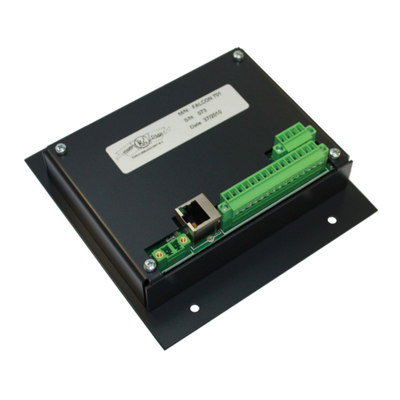
Page 31: Appendix B Connections F-701
Appendix B Connections F-701 Version: Date: 9 November 2010 Document: Falcon701 Ver01 Page 31 of 34 First release: 04 February 2010... -
Page 32: Appendix C Settings On Pcb
Appendix C Settings on PCB Version: Date: 9 November 2010 Document: Falcon701 Ver01 Page 32 of 34 First release: 04 February 2010... -
Page 33: Appendix D List Of Stations
Appendix D List of Stations Station nr. Location Sub / Main IP address 192.168.2…… □ □ 192.168.2…… □ □ 192.168.2…… □ □ 192.168.2…… □ □ 192.168.2…… □ □ 192.168.2…… □ □ 192.168.2…… □ □ 192.168.2…… □ □ 192.168.2…… □ □ 192.168.2……... - Page 34 Version: Date: 9 November 2010 Document: Falcon701 Ver01 Page 34 of 34 First release: 04 February 2010...
Need help?
Do you have a question about the Falcon F-701 and is the answer not in the manual?
Questions and answers