Advertisement
Available languages
Available languages
Advertisement
Table of Contents

Related Manuals for Radio Zeeland DMP Sigma 700

Summary of Contents for Radio Zeeland DMP Sigma 700
- Page 2 Waarschuwing Deze apparatuur is uitgerust met een hoogspanning EL lamp onder de folie en met hoogspanning elektronica in de behuizing om deze lamp aan te sturen. Maak geen krassen of andere beschadigingen op de folie en maak het apparaat niet open tijdens gebruik.
-
Page 3: Table Of Contents
INDEX PAGINA: Algemene beschrijving en technische gegevens Installatievoorschrift Aansluitingen Instellingen Bedieningsvoorschriften Probleem oplossing Maatvoering instrument Maatvoering inbouwframe Uitsnijmaten console Overzicht jumpers en dipswitches Aanlsuitingen overzicht Bedradingschema PAGE: General description and technical data Rules for installation Connections Settings Operating Instructions Troubleshooting Dimensions of the instrument Dimensions of the mounting frame Cut-out dimensions for the console... - Page 4 Controleer of de bovengenoemde items aanwezig zijn. Is dit niet het geval, neem dan zo snel mogelijk contact op met uw dealer. Lees voor het installeren van de Sigma 700 aandachtig deze manual door. Als er vragen of onduidelijkheden zijn, neem dan contact op met uw dealer.
-
Page 5: Installatievoorschrift
Installatievoorschrift GEBRUIK GEEN ANDERE DAN DE VOORGESCHREVEN POSTEN UIT DE SIGMA LIJN. Montage zichtinstrument Het zichtinstrument wordt zodanig geplaatst dat deze gemakkelijk bedienbaar is voor de roerganger. Er moet voldoende ruimte overblijven om de bekabeling te leggen. Een montage tekening is te vinden achter in deze manual. Op de intercom kan de éénmansbediening RZ 707 en de zwanenhalsmicrofoon RZ 704 worden aangesloten. -
Page 6: Aansluitingen
Aansluitingen K1: Voeding Sigma 700 Sluit de voedingsspanning aan op connector K1 met een afgeschermde kabel van minimaal 2 maal 2,5 mm K2: Lokale aansluitingen Screen K2-1 t/m 3: de externe luidspreker. (optioneel) Deze kan via een afgeschermde kabel aangesloten worden op connector K2. - Page 7 K2-5 t/m 6: de voetschakelaar. Hierop moet de (voet)schakelaar aangesloten worden. De aansluitingen zijn in bovenstaande figuur aangegeven. K2-7 t/m 9: relais contacten. Dit relais schakelt wanneer er een oproep binnenkomt en nog niet geaccepteerd is en er nog geen andere verbinding met het desbetreffende station is geaccepteerd. Dit is een potentiaal vrij contact.
-
Page 8: Instellingen
Instellingen Aantal posten. Om de lijn-impedantie en hiermee de kwaliteit van de signalen binnen het systeem op een acceptabele waarde te houden moet met dipswitch S1 een instelling worden gemaakt afhankelijk van het aantal posten in het totale systeem. Gemakshalve is in onderstaande tabel aangegeven welke schakelaartjes moeten worden gezet bij een bepaald aantal. -
Page 9: Bedieningsvoorschriften
De bijbehorende indicator gaat aan wanneer de post de oproep bevestigt. Op een Sigma 700 post moet een oproep bevestigd worden door het drukken van de toets waarvan de indicator knippert. Op een nevenpost wordt een oproep altijd automatisch bevestigd. -
Page 10: Probleem Oplossing
Probleem oplossing. Post doet niets: Sigma 700 (hoofdpost) staat uit. Voedingsspanning controleren bij post en eventueel er afhalen en er weer opzetten. Alle posten hebben een zelfherstellende zekering. Gebroken spraakverkeer: Er wordt te hard of te dichtbij in de microfoon gesproken. - Page 11 Check whether the above-mentioned items are present or not. If not, contact your dealer as soon as possible. Before installing the Sigma 700, carefully read this manual through. If you have any questions or need any clarifications, contact your dealer.
-
Page 12: Rules For Installation
Rules for installation USE ONLY PRESCRIBED ITEMS FROM THE SIGMA RANGE OF PRODUCTS. Installation of the display unit The display unit instrument installation should be installed in such a manner that the helmsman can easily operate it. There must be sufficient room for laying the cable. An installation drawing may be found at the back of this manual. -
Page 13: Connections
Connections K1: Power supply to the Sigma 700 Connect the supply voltage to the connector K1 with a screened cable of at least 2 times 2.5 mm K2: Local connections Screen K2-1 to 3: The external loudspeaker. (optional) This can be connected to the connector K2 via a screened cable. - Page 14 K2-5 to 6: The footswitch. The (foot)switch should be connected to this. The connections have been indicated in the figure above. K2-7 to 9: relay contacts. This relay is activated when a call comes in and has not been accepted as yet, and no other connection to the related station has been accepted.
-
Page 15: Settings
Settings Number of posts. In order to maintain the line impedance and therefore the quality of the signals within the system at an acceptable level, a setting should be made with the dipswitch S1 depending on the number of posts in the system as a whole. For convenience, the following table shows the types of switches that should be used for a specific number. -
Page 16: Operating Instructions
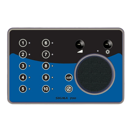
By pressing a button numbered from 1 to 10, a call is made to the post with that number. The related indicator switches on when the post confirms the call. On a Sigma 700 post, a call should be confirmed by pressing the key the indicator of which is flashing. A call is always automatically confirmed at a secondary post. -
Page 17: Troubleshooting
Troubleshooting. Post not operating: The Sigma 700 (main post) is switched off. Check the supply voltage of the post and if necessary switch it off and then on again. All the posts have a self-resetting fuse. Interrupted speech traffic: Speech is taking place too close to the microphone. There is harmonic noise due to wind or resonance. - Page 18 89,6 35,4...
- Page 21 K3-04 K3-03 K3-02 K3-01 K2-12 K2-11 K2-10 K2-09 K2-08 K2-07 K2-06 K2-05 K2-04 K2-03 K2-02 K2-01 K1-05 K1-04 K1-03 K1-02 K1-01...
- Page 22 LINE B K3- 04 LINE A K3- 03 LINE B K3- 02 LINE A K3- 01 Screen MIC 2 K2- 12 MIC 1 MICROPHONE K2- 11 K2- 10 RE2 NC K2- 09 RE2 C ALARM OUTPUT K2- 08 RE2 ON K2- 07 K2- 06 FOOTSWITCH...
Need help?
Do you have a question about the Sigma 700 and is the answer not in the manual?
Questions and answers