
Related Manuals for hager unimes H U-PW powerway


Summary of Contents for hager unimes H U-PW powerway
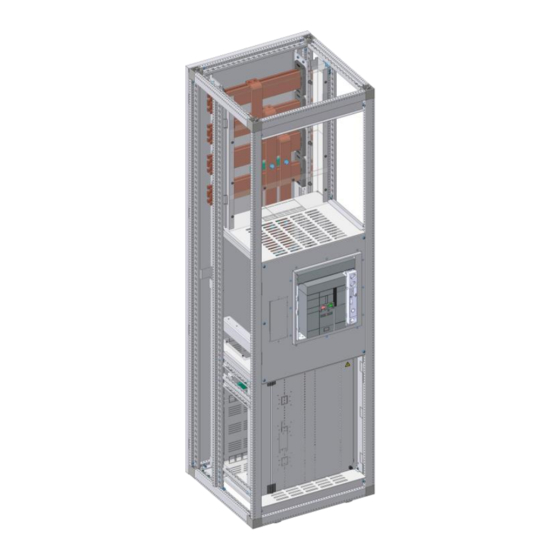
- Page 1 System Manual Power distribution system unimes H U-PW powerway ACB incoming, outgoing, coupling enclosure 473-784-152...
-
Page 3: Table Of Contents
Inhaltsverzeichnis About this manual 01.01 Subject of the manual ......................06 01.02 Related documents ......................07 01.03 Imprint ..........................08 01.04 Symbols and warning signs used ..................09 01.05 Abbreviations ........................10 Safety 02.01 Intended use ........................16 02.02 Misuse ..........................16 02.03 General safety instructions .................... - Page 4 Inhaltsverzeichnis 04.05 Information on mounting enclosures in the installation position ......... 67 04.06 Sequence of assembly steps ..................... 68 Operation and use of the circuit breakers 05.01 Personnel requirements ..................... 72 05.02 hw+ circuit breakers - Quick guide ..................73 Inspection and maintenance 06.01 Maintenance........................
-
Page 6: About This Manual
01 About this manual This manual is part of the unimes H enclosure system. It describes the “UPW powerway” enclosure types of the unimes H power distribution system: – U-PWE - ACB incoming/outgoing enclosure – U-PWK - ACB coupling enclosure NOTE These enclosure types are referred to hereafter as 'powerway enclosures', or 'powerway enclosure'. - Page 7 Page Subject of the manual Related documents Imprint Symbols and warning signs used Abbreviations...
-
Page 8: Subject Of The Manual
About this manual Subject of the manual 01.01 Subject of the manual Users This document is intended for users of powerway enclosures: Planners, manufacturers, operators and users of switchgear and controlgear assemblies according to EN 614391/2. The manual also contains information regarding the efficient use of enclosures, as well as guidance on intended use, structure, function, mounting, installation, and operation, along with technical data. -
Page 9: Related Documents
Planner – unimes H power distribution system manual – Hager catalogues for power distribution systems with technical information – Component selection, lists, and production drawings from the “hagercad” planning software – Guidelines for project planning and design of switchgear according to DIN EN 61439 (VDE 06600-600) –... -
Page 10: Imprint
Product names, company names, trademarks or registered trademarks are the property of their respective owners and must be treated as such. The manual does not extend the Sales and Delivery Conditions of Hager. No new claims concerning the warranty and guarantee, which extend beyond the Sales and Delivery Conditions, can be derived from this manual. -
Page 11: Symbols And Warning Signs Used
About this manual Symbols and warning signs used 01.04 Symbols and warning signs used Warning messages Signal word Type and source of the hazard Consequences if the hazard is ignored Measures for averting the hazard. Warning messages include a specific hazard symbol in the left column. The right column contains the warning text consisting of: 1. -
Page 12: Abbreviations
About this manual Abbreviations 01.05 Abbreviations Air circuit breaker Type designation of the overcurrent relay integrated in the TemPower2 ACB Position signalling switch cos φ Phase shift Current transformer Drawable (a plug connection that can be released without the use of tools), see glossary for explanation Low-voltage switchgear and controlgear assembly in accordance with DIN EN 61439-1/-3 (Distribution board intended to be operated by ordinary persons) - Page 13 About this manual Abbreviations Neutral conductor Low-voltage high rupturing capacity... HRC-F Low-voltage high rupturing capacity fuse N-phase protection on OCR Neutral conductor disconnector Overcurrent relay Protective earth Division unit Switchgear and controlgear assembly in accordance with DIN EN 61439-1/-2 (Power Switchgear and Controlgear assembly) PSCSGK Power Switchgear and controlgear assembly, can only be operated by a qualified electrician/electrically instructed person (under the supervision of a qualified electrician), cannot be...
- Page 14 About this manual Abbreviations Distribution enclosure Plug-in insertion technology or withdrawable connection. Plug-in insertion technology: Input and outlet plugged in, auxiliary circuit must be connected or disconnected by hand. Also known as withdrawable technology. Insertion technology: Input, outlet and auxiliary circuit plugged in. Wall-mounted enclosure U-PW powerway System Manual...
-
Page 16: Safety
02 Safety Read carefully Observe the safety information in the system manual for the unimes H power distribution system. Observe the safety information in the operating instructions of the components used. The information about intended use as provided in this section should also be taken into ac- count. - Page 17 Page Intended use Misuse General safety instructions...
-
Page 18: Intended Use
02.02 Misuse Misuse Any use deviating from the intended use is considered misuse. Hager does not assume any liability for damages resulting from misuse. DANGER! Danger due to electric shock or arc faults Misuse can result in high voltages and high currents, which can lead to dangerous situations. -
Page 19: General Safety Instructions
Safety General safety instructions 02.03 General safety instructions Electrical hazards DANGER Electric shock An electric shock results in serious burns and life-threatening injuries and even death. Prior to starting work on the system, observe the following 5 safety rules: ... -
Page 20: Powerway Enclosures And Components
03 powerway enclosures and components Properties and technical data of the powerway enclosures and mountable components. - Page 21 Page System overview Technical data Type key Order overviews Component overview Spatial distribution Partition concept Configuration of enclosure front U-PWE/U-PWK...
-
Page 22: System Overview
powerway enclosures and components System overview 03.01 System overview powerway enclosures U-PWE U-PWK Incoming and outgoing enclosure Coupling enclosure System solutions hw+ series air circuit breaker (HW1) Enclosure rated voltage ≤ 690 V AC Expansion technology – Plug-in technology/fixed installation (version -F) FFF, FFD/HW1 –... -
Page 23: Technical Data
powerway enclosures and components Technical data 03.02 Technical data 03.02.01 unimes H General characteristic features of the switchgear and controlgear assembly interfaces Degree of pollution Installation site Fixed indoor installation Protection type – Devices can be operated from the outsi- ≤... -
Page 24: Powerway Enclosures
powerway enclosures and components Technical data Type of functional unit design Plug-in technology/fixed installation -F Device input and device outlet with fixed connection technology: FFF, FFD Plug-in technology -R Device input with guided connection technology, device outlet with fixed connection technology: WFF, WFD Plug-in insertion technology -W Device input and device outlet with guided connection technology, auxiliary circuit can be plugged in by hand: WWD... -
Page 25: Type Key
powerway enclosures and components Type key 03.03 Type key Type key standard version (Form 1) — Enclosure versions Incoming/outgoing enclosure Coupling enclosure U-PW powerway System Manual... -
Page 26: Order Overviews
powerway enclosures and components Order overviews 03.04 Order overviews Basic enclosures U-PWE - Cable entry bottom U-PWE - Cable entry top U-PWK U-PWE - Incoming, outgoing, basic enclosure Width Height Depth Cable entry Reference 600 mm 2000 mm 600 mm bottom U-PWEZU606020 600 mm... -
Page 27: Component Overview
powerway enclosures and components Component overview 03.05 Component overview Functional units Expansion stage (extended partition) Support frame for ACB mounting Expansion stage (blank partition) Device field partition, H-SaS Device field partition, cable entry FG bar with attachment U-PW powerway System Manual... -
Page 28: Spatial Distribution
powerway enclosures and components Spatial distribution 03.06 Spatial distribution Spatial distribution according to EN 61439-1/-2 up to Form 4b The powerway enclosures are characterised by clear and well-arranged spatial distribution. The spatial distribution enables the extension of the internal separation according to EN 61439-1/-2 up to Form 4b. - Page 29 powerway enclosures and components Partition concept Extended partition Device field partition Frame covers (trough) Blank partition H-SaS top/bottom, cable entry bottom/top Front view H-SaS top, cable entry bottom H-SaS bottom, cable entry top U-PW powerway System Manual...
- Page 30 powerway enclosures and components Partition concept H-SaS top/bottom, cable entry, H-SaS separate H-SaS top, cable entry bot- H-SaS bottom, cable entry H-SaS top, cable entry bot- H-SaS bottom, cable entry tom, H-SaS separate bottom top, H-SaS separate top tom, H-SaS separate middle top, H-SaS separate middle U-PW powerway System Manual...
- Page 31 powerway enclosures and components Partition concept H-SaS top, cable entry top/H-SaS bottom, cable entry bottom Front view H-SaS top, cable entry top H-SaS bottom, cable entry bottom U-PW powerway System Manual...
- Page 32 powerway enclosures and components Partition concept H-SaS top, cable entry top/H-SaS bottom, cable entry bottom/H-SaS separate H-SaS top, cable entry top, H-SaS bottom, cable entry H-SaS top, cable entry top, H-SaS bottom, cable entry H-SaS separate bottom bottom, H-SaS separate top H-SaS separate middle bottom, H-SaS separate mi- ddle...
- Page 33 powerway enclosures and components Partition concept H-SaS middle, cable entry Front view H-SaS middle, cable entry bottom H-SaS middle, cable entry top U-PW powerway System Manual...
- Page 34 powerway enclosures and components Partition concept H-SaS middle, cable entry, H-SaS separate H-SaS middle, cable entry bottom, H-SaS middle, cable entry top, H-SaS H-SaS separate separate U-PW powerway System Manual...
- Page 35 powerway enclosures and components Partition concept H-SaS top/bottom Front view H-SaS top, H-SaS bottom U-PW powerway System Manual...
- Page 36 powerway enclosures and components Partition concept H-SaS top/middle/bottom Front view H-SaS top, H-SaS middle H-SaS middle, H-SaS bottom U-PW powerway System Manual...
- Page 37 powerway enclosures and components Partition concept Additional information on the partition concept There are two design options in the case of ex- tended partitions – Extended partition as shown on the left. – Control compartment without extended par- tition, this enables the installation of large current transformers that are easy to access for example.
-
Page 38: Configuration Of Enclosure Front
powerway enclosures and components Configuration of enclosure front 03.08 Configuration of enclosure front U-PWE/U-PWK front installation version (FE1) – Device access and device operation in enclosure front – Device status visible – Available with and without convection – Form of internal separation: –... - Page 39 powerway enclosures and components Configuration of enclosure front Enclosure front with ACB door flange – A door flange must always be mounted in the case of the front installation version (FE1). – Meets the requirements for protection type IP3X. Front side Rear side Description Door flange for ACB, withdrawable...
-
Page 40: U-Pwe/U-Pwk
powerway enclosures and components U-PWE/U-PWK 03.09 U-PWE/U-PWK ACB incoming/outgoing/coupling enclosure 630-1600 A Area of application – Incoming units, outgoing units up to 1600 A – Cable outlets up to 1600 A – Cross couplings up to 1600 A Design options –... - Page 41 powerway enclosures and components U-PWE/U-PWK Miscellaneous Form of internal separation Solid door 2b, 3b, 4b 3 module doors Device operation Can be operated from the outside Can be operated behind the door Type of functional unit design Plug-in technology/fixed installation -F FFF/FFD Plug-in insertion technology -W Enclosure colour...
- Page 42 powerway enclosures and components U-PWE/U-PWK Device compartment Control compartment Module heights 12 MU = 600 mm Expansion – Control compartment, swivelled (mounting plate) – Control compartment, fixed (clear polycarbonate plate) Derating factors ACB Derating factors I for incoming, outgoing and cross coupling unit function at 35°C ambient tempe- rature in protection type version IP2x, IP3x and IP4x.
-
Page 43: Versions And Applications
powerway enclosures and components U-PWE/U-PWK 03.09.01 Versions and applications Key for diagrams below H = Main bus bar Z = Feed (cable entry roof or base) O = Position of the main busbar/feed 'top' U = Position of the main busbar/feed 'bottom' M = Position of the main busbar/feed 'middle' Incoming, outgoing enclosure 3P+N (NT_ND) Enclosure heights 2000 and 2200 mm... - Page 44 powerway enclosures and components U-PWE/U-PWK Incoming, outgoing enclosure 4P Enclosure heights 2000 and 2200 mm HO/ZU HU/ZO HM/ZO HM/ZU Incoming, outgoing enclosure 3P Enclosure heights 2000 and 2200 mm HO/ZU HU/ZO HM/ZO HM/ZU U-PW powerway System Manual...
- Page 45 powerway enclosures and components U-PWE/U-PWK Coupling enclosure 3P + N (NT_ND) Enclosure heights 2000 and 2200 mm HO/HU HO/HM HU/HM Coupling enclosure 4P Enclosure heights 2000 and 2200 mm HO/HU HO/HM HU/HM U-PW powerway System Manual...
- Page 46 powerway enclosures and components U-PWE/U-PWK Coupling enclosure 3P Enclosure heights 2000 and 2200 mm HO/HU HO/HM HU/HM U-PW powerway System Manual...
- Page 47 powerway enclosures and components U-PWE/U-PWK 03.09.02 Main busbar system H-SaS Installation positions of the H-SaS The main busbars can be positioned at three different heights on the unimes H. This makes it possible to install up to three main busbar systems (H-SaS) in the enclosure. Two main busbar systems may be loaded simultaneously in this case.
- Page 48 powerway enclosures and components U-PWE/U-PWK Electrical features of the H-SaS Enclosure depth 600 mm 800 mm Rated current per busbar system initial ≤ 2950 A ≤ 4000 A supply Rated current I 2x 30 x 10: 1250 A (H-SaS top) 2x 40 x 10: 1600 A 2x 60 x 10: 2000 A 2x 80 x 10: 2850 A...
- Page 49 powerway enclosures and components U-PWE/U-PWK Enclosure depth 600 mm 800 mm H-SaS with round hole H-SaS with elongated hole Rated peak withstand current I (1 s) 2x 30 x 10: 133 kA (system-related distance between 2x 40 x 10: 145 kA supports) 2x 60 x 10: 188 kA 4x 60 x 10: 188 kA...
- Page 50 – Distances of the cable / rail connections on the ACB Enclosure-type-specific production drawings Hager provides the switchgear manufacturer with enclosure type-specific assembly drawings and in- dividual component drawings for producing the individual copper parts. The switchgear manufacturer produces the individual copper parts before the switching enclosures are delivered.
- Page 51 powerway enclosures and components U-PWE/U-PWK 03.09.04 Connection to H-SaS and ACB Centre-to-centre distance between phases of connection to H-SaS - HW1XXXXXX Switch type HW1XXXXXX Rated current I ≤ 1600 A Terminal conductor distance at ACB 70 mm Terminal conductor distance of connection 70 mm to H-SaS Maximum space for transformer...
-
Page 52: Examples Of Field Connection/Coppering
powerway enclosures and components U-PWE/U-PWK 03.09.05 Examples of field connection/coppering Example: U-PWE 3-pole Example: U-PWK 3-pole U-PW powerway System Manual... - Page 53 powerway enclosures and components U-PWE/U-PWK 03.09.06 ACB and functional units Connections on ACB in the incoming enclosure Connections bottom Version Input Required connections (top and bottom) -F/FE1 from the from the bottom -F/HF from the from the bottom -W/FE1 from the from the bottom -W/HF...
- Page 54 powerway enclosures and components U-PWE/U-PWK ACB connections Description Position Number of terminals Product code Long rear top/bottom HWY148H connection, 152 mm HWY149H Short rear top/bottom HWY048H connection, 60 mm HWY049H Front connection -W top/bottom HWY044H HWY045H Front connection -F top/bottom HWY040H HWY041H U-PW powerway System Manual...
-
Page 55: Current Transformer Installation Options
Installation positions of approved current transformers Current transformers for 800 A Current transformers for 1600 A Manufactu Manufactu Item Type Item Type Position Position Hager SRD08005 Hager SRE16005 ASK 51.4 Hager SRF16005 ASK 561.4 ASK 63.4 ASK 63.4 ASK 63.6 ASK 63.6... - Page 56 powerway enclosures and components U-PWE/U-PWK Installation option 1+ 2 Installation option 1 Installation option 2 Example: 553-200-624 Example: 553-202-624 U-PW powerway System Manual...
- Page 57 powerway enclosures and components U-PWE/U-PWK Installation option 3+ 4 Installation option 3 Installation option 4 Example: 553-212-624 Example: 553-215-624 Installation option 5+ 6 Installation option 5 Installation option 6 Example: 553-216-624 Example: 553-219-624 U-PW powerway System Manual...
- Page 58 powerway enclosures and components U-PWE/U-PWK 03.09.08 Functional units Control compartment, fixed or swivelled The control compartment is used to cover the field connections or the terminal compartment. The powerway enclosures can be extended with up to two control compartments (installation at top and bottom).
-
Page 59: Cross-Connection Space/Auxiliary Circuit Wiring
powerway enclosures and components U-PWE/U-PWK 03.09.09 Cross-connection space/auxiliary circuit wiring Cross-connection space/auxiliary circuit wiring The auxiliary circuit wiring/cross-wiring is contained inside the enclosure: – in plastic pipes (KIR, KRH), – in plastic cable conduits/grid conduits. The optional auxiliary power wiring/cross-wiring on the enclosure roof is contained within a metal cab- le conduit (on a pre-perforated cover plate). - Page 60 powerway enclosures and components U-PWE/U-PWK Cross-wiring in the enclosure Front Side – The vertical auxiliary circuit can be routed along the supports (on the left and right of the device com- partment) depending on the enclosure design. – The horizontal circuit can be routed above and below the ACB. It is also possible to connect the auxili- ary circuit from the switch/circuit breaker to the terminals at the top and bottom of the enclosure.
-
Page 62: Project Planning And Mounting
04 Project planning and mounting When mounting, always also refer to the installation manual supplied with the components. - Page 63 Page Operating safety and system availability Electrical connection Forms of internal separation Securing escape and emergency routes Information on mounting enclosures in the installation position Sequence of assembly steps...
-
Page 64: Operating Safety And System Availability
Project planning and mounting Operating safety and system availability 04.01 Operating safety and system availability Applicable regulations and laws German Ordinance on Heavy Current (StV): Equipment/material for working on high-voltage systems German Accident Prevention Regulations (VUV): The employer must make reasonable personal protective equipment (PPE) available Product Safety Act (PrSG): –... -
Page 65: Electrical Connection
Project planning and mounting Electrical connection Working methods for electrical engineering work Basically, a distinction is made between three working methods for working on electrical systems: Method 1 Work in a de-energised condition (disconnected) Method 2 Work in the vicinity of live parts –... - Page 66 Project planning and mounting Electrical connection Electrical connection - Overview and personnel qualifications Plug-in technology/fixed installation -F Main power circuit – With permanently installed functional units – Permanently connected input and outlet Auxiliary circuit – Permanently installed or plugged in Connection according to EN 61439-1 –...
- Page 67 Project planning and mounting Electrical connection Insertion technology -W Main power circuit – With functional units which are switched from the opera- ting position to the disconnected position – Input plugged in – Outlet plugged in Auxiliary circuit – Plugged in Connection according to EN 61439-2 –...
-
Page 68: Forms Of Internal Separation
Project planning and mounting Forms of internal separation 04.03 Forms of internal separation Forms of internal separation according to EN 61439 Form Internal separation Connections for conductors brought Symbol in from the outside none between busbars and functional not divided by the busbars units divided by the busbars –... -
Page 69: Securing Escape And Emergency Routes
Project planning and mounting Securing escape and emergency routes 04.04 Securing escape and emergency routes Securing escape and emergency routes When planning and installing low-voltage switchgear, the necessary escape and emergency routes must be observed. Particular attention must be paid to the use of doors on the enclosures: The doors must always close in the escape direction as they will block the escape route otherwise. -
Page 70: Sequence Of Assembly Steps
Project planning and mounting Sequence of assembly steps Maintaining free spaces Maintain the required free spaces (minimum specifications): – Minimum spacing of cabinet surface to the ceiling: 500 mm – Minimum passage height below covers or enclosures: 2000 mm –... -
Page 72: Operation And Use Of The Circuit Breakers
05 Operation and use of the circuit breakers Refer to the technical catalogue for the hw+ series air circuit breakers. Refer to the installation manual for the hw+ series air circuit breakers. - Page 73 Page Personnel requirements hw+ circuit breakers - Quick guide...
-
Page 74: Personnel Requirements
Operation and use of the circuit breakers Personnel requirements 05.01 Personnel requirements Operation of the systems Operation includes all activities that are necessary for the electrical system to function. This includes: – Switching, – Monitoring, – Performing tests and configuring settings, –... -
Page 75: Hw+ Circuit Breakers - Quick Guide
Operation and use of the circuit breakers hw+ circuit breakers - Quick guide Observing the documentation for the unimes H system Information Observe the safety information and further instructions in the System Manual for the unimes H power distribution system: - What to do in case of faults - Repairs - Cleaning... - Page 76 Operation and use of the circuit breakers hw+ circuit breakers - Quick guide Overview of circuit breakers and load break switches Fixed version, 3 terminals Fixed version, 4 terminals Withdrawable version, 3 terminals Withdrawable version, 4 terminals Categories of accessories Control ac- Signalling ac- Accessories for interlo-...
- Page 77 Operation and use of the circuit breakers hw+ circuit breakers - Quick guide Overview of electronic tripping unit sentinel LSIG Switching enclosure integration The hw+ circuit breakers and load break switches are generally used as low-voltage protection in the installation’s incoming area. Various assembly methods and connection types are available to increase installation flexibility.
-
Page 78: Inspection And Maintenance
06 Inspection and maintenance Important safety note Read and take note of the sections "For your safety" and "Inspection and maintenance" in the System Manual for the unimes H power distribution system. Read the instruction manual accompanying the ACB. - Page 79 Page Maintenance...
-
Page 80: Maintenance
– Hager Hager Service In order to ensure its systems operate with a high degree of reliability, Hager offers a maintenance and service concept implemented by qualified service technicians that conforms to standards. These ser- vices include commissioning, conversion and maintenance. -
Page 81: Index
Index 07 Index Abbreviations ..............10 Related documents ............07 About this manual ............04 ACB and functional units ..........51 Safety ................ 04, 14 Securing escape and emergency routes ......67 Component overview............25 Sequence of assembly steps .......... 68 Configuration of enclosure front ........ - Page 82 Hager AG Chemin du Petit-Flon 31 1052 Le Mont-sur-Lausanne Switzerland T +41 21 644 37 00 lausanne@hager.com hager.ch Hager Vertriebsgesellschaft mbH & Co. KG Zum Gunterstal 66440 Blieskastel Germany T +49 6842 945 0 F +49 6842 945 4625 hager.de Hager Polo Sp.
Need help?
Do you have a question about the unimes H U-PW powerway and is the answer not in the manual?
Questions and answers