
Related Manuals for MegaTec MT-LA-MP


Summary of Contents for MegaTec MT-LA-MP
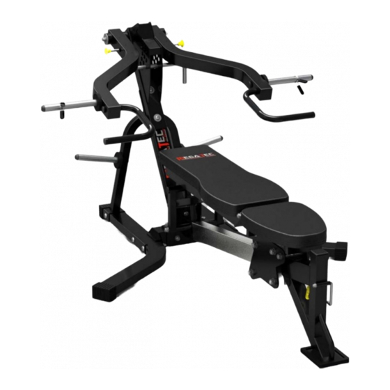
- Page 1 MEGATEC Lever Arm Multi Press MT-LA-MP Assembly Walkthrough The Megatec Lever Arm Multi Press comes in 2 boxes. The dimensions are: Carton 1 Carton 2 Length Width Depth Length Width Depth 1.42 0.32 0.44 1.06 0.70 0.21...
- Page 2 Unpack the boxes and place all the parts on the ground. You will also have the pack with all the nuts and bolts in it.
- Page 3 It would be great idea to label the hardware packs at the beginning. You can use the instructions to do this. NOTE: Do not tighten the nuts and bolts until the end, unless told otherwise. Some of the parts may also come pre installed.
- Page 4 Part #14 Plate #13 Bolts #4 You can then connect both parts #14 to either side of #12 using #4 bolts and #13 plates.
- Page 5 Part #19 Bolt #3 Part #14 Bolt together Part #19 to either side of #14 using #3 bolts.
- Page 7 Part #15 Bolt #9 Part #12 Part #15 can then bolted on at the bottom with Part #12 using #9 bolts. Part #15 Part #19 Bolts #6 Part #15 also needs to be bolted to the top of #19 using #6 bolts.
- Page 8 Part #19 Part #34 Bolt #5 Part #34 can be bolted onto #19 using #5 bolt. Once it is tight, you can then place the rubber ring on.
- Page 9 Bolts #7 Part #17 Part #15 Part #17 is placed through the top of #15 and then bolted in the back by #7 bolts. Part #20 Part #15 Then you place Part #20 into one of the adjustment holes on #15.
- Page 10 Part #17 Part #16 You can then place the arms Part #16 onto the axle Part #17. Please ensure that the rubber strip is on the underside of the bench arm. Part #16 Part #18 Each arm Part #16 can then be locked on with Part #18 and then bolted on.
- Page 11 Part #23 Bolts #8 Part #23 can be bolted on using #8 bolts. Part #24 Bolts #7 Part #24 can be bolted on using #7 bolts.
- Page 12 Bolts #8 Bolts #8 Bolts #8...
- Page 13 Bolts #7...
Need help?
Do you have a question about the MT-LA-MP and is the answer not in the manual?
Questions and answers