Table of Contents
Advertisement
Quick Links
INSTALLATION INSTRUCTIONS
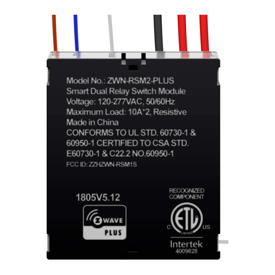
ZWN-RSM2
Smart Dual Relay Switch Module
SPECIFICATIONS
Voltage.........................................................................120-277VAC, 50/60Hz
Maximum Load requirement.................................................................10A×2
Z-Wave Frequency.............................................................. 908.42MHz(US)
Operating Temperature..............................................................32° F-104° F
Size................................................................................2.02'' ×1.71'' ×0.62''
Range...................................................................Up to 100 feet line of sight
between the Wireless Controller and the closest Z-Wave receiver module.
FEATURES
Work with existing light switches, required neutral wire
Slim size module with build in Z-Wave technology
Acts as a Z-Wave repeater to extend the range
On/Off control via Z-Wave controller, manual wall switch
3 way wiring compatible
DESCRIPTION
Z-Wave unifies all your home electronics into an integrated wireless network
and helps them talk to each other. Any Z-Wave enabled item can be added
to the network, and making your home electronics fully compatible.
The ZWN-RSM2 Switch Module is a component of lighting control system, it
can not be used separately but should turn an existing switch into a Z-Wave
switch. This ZWN-RSM2 module is a Z-Wave enabled device and is fully
compatible with any Z-Wave enabled network. In a Z-Wave network, each
device is designed to act as a wireless repeater. Once the ZWN-RSM2 module
is installed and setup with in your wall, it will retransmit the RF signal from one
device to another until the
intended device is reached. This ensures that the
signal is received by its intended destination by routing the signal around
obstacles and radio dead spots.
-01-
WARNINGS AND CAUTIONS
To be installed and/or used in accordance with appropriate electrical codes
and regulations. Exercise extreme caution when using Z-Wave devices to
control appliances. Operation of the Z-Wave device may be in a different
room than the controlled appliance, also an unintentional activation may
occur if the wrong button on the remote is pressed. Z-Wave devices may
automatically be powered on due to timed event programming.Depending
upon the appliance, these unattended or unintentional operation could
possibly result in a hazardous condition.
Z-Wave enabled devices should never be used to supply power to, or
control the On/Off status of medical and/or life support equipment.
If you are unsure or uncomfortable about performing the installation,
please consult a qualified electrician.
INSTALLATION
Wiring Diagram:
Load 2
Load 1
Hot
Neutral
Aux 2
Aux 1
IMPORTANT NOTE ABOUT 3-WAY CIRCUITS
The term "3-way circuit" refers to a circuit with two switches and one load (light)
like you find at the top and bottom of a stairway. There are many ways to physically
wire a 3-way circuit and it is important to understand how the circuit you wish to
upgrade to Z-Wave control is wired. Below is a description of a typical 3-way circuit.
One of the ways to wire a two-switch/one-load circuit is to route the incoming power
through the first switch, then to the second switch and then to the load. Although very
common and by no means a standard, it is the easiest to convert to Z-Wave control.
Technically switch 2 and switch 4 are in the same location, so ZWN-RSM2 is set
behind them. Do not change the wiring of switch 1 and switch 3. Please note that
all the switches must be 3-way switch.
-02-
Typical 3-way circuit:
Please consult an electrician if you have trouble identifying the type of wiring
circuit you wish to convert or if you do not feel confident in your ability to
convert the circuit to Z-Wave control.
Neutral
Neutral
Line
(Black)
Neutral
(White)
Switch 2
Line
Line
Switch 1
1. WARNING: To avoid fire, shock, or death. Turn off power at circuit breaker
or fuse and test that power is off before wiring.
2. Remove wall plate and switches mounting screws.
3. Carefully remove these existing switches from the switch box.
4. Disconnect the wiring from these existing switches.
5. Connect the ZWN-RSM2 module as shown in the wiring diagram.
6. Check connections to be sure they are tight and no bare conductors are exposed.
7. Insert the ZWN-RSM2 module into the box first
8. Attach the wall plate.
9. Restore power at the circuit breaker and test the system.
Black
Black
Red
Yellow
Switch 1
Switch 2
White
Load 2
Neutral
Load 1
Neutral
Hot
Line
(Black)
Neutral
Neutral
(White)
Switch 4
Switch 3
Aux 2
Aux 1
Switch 2
Switch 1
, then wire these existing switches.
-03-
Line
Line
Advertisement
Table of Contents

Subscribe to Our Youtube Channel
Related Manuals for Lorenz ZWN-RSM2

Summary of Contents for Lorenz ZWN-RSM2
- Page 1 RF signal from one Technically switch 2 and switch 4 are in the same location, so ZWN-RSM2 is set 7. Insert the ZWN-RSM2 module into the box first , then wire these existing switches.
- Page 2 Remote Control or cost of removal, installation or reinstallation. When the ZWN-RSM2 switch module is included in a Z-Wave network, it can be WIRELESS RANGE Mar, 2014 turned on/off remotely by a portable controller or a Z-Wave enabled gateway 11031A controller.
Need help?
Do you have a question about the ZWN-RSM2 and is the answer not in the manual?
Questions and answers