Table of Contents
Advertisement
Advertisement
Table of Contents

Subscribe to Our Youtube Channel
Related Manuals for Smipack FP560


Summary of Contents for Smipack FP560
- Page 3 Use and maintenance manual FP560 - FP560A - FP870A USE AND MAINTENANCE MANUAL Manual or semi-automatic L-sealer FPF560 - P560A - FP870A MANUAL CODE: DM210702 DATE OF CREATION: 23.10.2012 REVISION: VERSION DATE: 10.09.2014...
- Page 4 This manual can be used for the model FP560 - FP560A - FP870A. It has been drawn up to put you in conditions to be able to intervene on the various parts, and to understand the various maintenance and intervention operations.
-
Page 5: Ce Declaration Of Conformity
(Directive 2006/42/EC - Annex IIA) Company name and address of manufacturer of the machine : SMIPACK S.p.A. - Via Piazzalunga, 30 - 24015 S. Giovanni Bianco (BG) - ITALY Tel. +39.0345.40400 - Fax +39.0345.40409 Name and address of the company authorized to compile the technical documentation : S.L.M. - Page 6 White page...
-
Page 7: Table Of Contents
Use and maintenance manual FP560 - FP560A - FP870A SUMMARY CE DECLARATION OF CONFORMITY ..............................5 GENERAL STANDARDS AND RECOMMENDATIONS ......9 HOW TO READ AND USE THE MANUAL ......................9 WARRANTY AND EXCLUSION OF LIABILITY ....................9 REFERENTIAL STANDARDS .........................10 SYMBOLS KEY ...............................10 MACHINE INSTALLATION ...............13... - Page 8 CLEANING AND MAINTENANCE ............43 GENERAL WARNINGS AND PRECAUTIONS ....................43 NATURE AND FREQUENCY OF MAINTENANCE CHECKS AND INTERVENTIONS ........45 REPLACING SEALING BLADE ........................45 REPLACING PTFE AND SILICON RUBBER ....................46 CHECKING THE LEVEL OF COOLANT ......................47 ACCESS TO ELECTRICAL PANEL ........................47 MACHINE ACCESS AREAS FOR INSPECTIONS ..................48 ANOMALIES AND FAULTS - HOW TO RESOLVE ........49 SOLUTIONS TO OPERATING PROBLEMS ....................49 ERROR AND MESSAGE DISPLAYS ......................49...
-
Page 9: General Standards And Recommendations
(operators and maintenance personnel) so that they may be consulted promptly when circumstances require it. SMIPACK S.p.A. will not be held liable for possible faults, accidents or problems due to failure to comply with the provisions contained in this user manual or caused by unauthorised modifications and installations of accessories. -
Page 10: Referential Standards
365 day validity starting from the date of purchase. During the period covered by warranty, SMIPACK commits itself to remove any faults or defects as long as periodical maintenance is performed and original parts are always used. Expendable materials, parts subject to normal wear or breakage, faults caused by atmospheric agents, transporting the machine to an assistance centre and labour charges are excluded from the warranty. - Page 11 Use and maintenance manual FP560 - FP560A - FP870A N.B.! This indicates useful information for consultation of the manual and proper operation of the machine. WARNING! This indicates situations of risk for the machine and/or for the product being processed.
- Page 12 Chapter 1 - General standards and recommendations USE OF SAFETY FOOTWEAR COMPULSORY USE OF HEARING PROTECTION COMPULSORY USE OF GLOVES COMPULSORY CLOTHING COMPULSORY GOGGLES COMPULSORY...
-
Page 13: Machine Installation
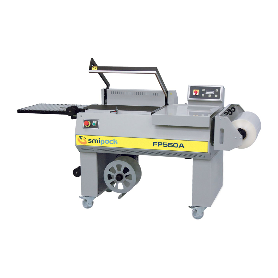
Use and maintenance manual FP560 - FP560A - FP870A CHAPTER 2 - MACHINE INSTALLATION 2.1 DESCRIPTION OF THE MACHINE COMPONENTS A) MODEL FP560 REEL HOLDER ELECTROMAGNET FILM PERFORATORS CYCLE START MICROSWITCH INFEED PRODUCT-HOLDING COOLING UNIT PLATE SEALING FRAME OUTFEED CONVEYOR BELT... - Page 14 Chapter 2 - Machine installation B) MODEL FP560A - FP870A REEL HOLDER OPERATOR PANEL FILM PERFORATORS CYCLE START MICROSWITCH INFEED PRODUCT-HOLDING COOLING UNIT PLATE SEALING FRAME OUTFEED CONVEYOR BELT SEALING BLADE PACK DEVIATION DEVICE ELECTRICAL PANEL ROLLER UNIT FILM SCRAP COLLECTION DEVICE MASTER SWITCH (optional) Fig.
-
Page 15: Weight And Dimensions Of Packed Machine
Use and maintenance manual FP560 - FP560A - FP870A 2.2 WEIGHT AND DIMENSIONS OF PACKED MACHINE Fig. 2.2.1 X (mm) Y (mm) H (mm) WEIGHT (kg) 1400 1160 FP560 FP560A 1400 1160 2125 1110 1293 FP870A 2.3 MACHINE WEIGHT AND DIMENSIONS Fig. -
Page 16: Transportation And Unpacking
Chapter 2 - Machine installation 2.4 TRANSPORTATION AND UNPACKING SMIPACK S.p.A., depending on the type of transportation and products to be delivered, uses adequate packaging to guarantee integrity and preservation during transportation. Handle with care when transporting and positioning the machine. - Page 17 Use and maintenance manual FP560 - FP560A - FP870A Attention! Mount the two wheels A equipped with brakes at the front of the machine. 2) ASSEMBLY OF THE REEL HOLDER • Put the reel holder support (1) in the relative guides.
- Page 18 Chapter 2 - Machine installation • During assembly and disassembly avoid pushing the roller conveyor sideways in order not to damage its couplings. Fig. 2.5.4 4) INSTALLATION OF THE SCRAP COLLECTION DEVICE a) MOUNTING THE FILM SCRAP COLLECTION DEVICE • Apply screws 1 on machine support B, being careful not to tighten them in order to facilitate the subsequent operations.
- Page 19 Use and maintenance manual FP560 - FP560A - FP870A b) MOUNTING THE FILM SCRAP TRANSMISSION ROLLERS • Mount the two film scrap tensioning rollers 4 and 5 in the relevant pre-drilled holes on the machine as indicated in the figure.
-
Page 20: Electrical Connection
Chapter 2 - Machine installation Fig. 2.5.8 5) ASSEMBLY OF THE PACK DEVIATOR DEVICE • Screw the pack deviator device 7 into the prepared hole on the machine as shown in the figure. Fig. 2.5.9 2.6 ELECTRICAL CONNECTION Power must be cut from the machine for all operations involving connection to the electrical network. -
Page 21: Electrical Installation Data
Use and maintenance manual FP560 - FP560A - FP870A 2.7 ELECTRICAL INSTALLATION DATA Install a circuit breaker on the machine power supply line which supports the values indicated in the table. FP560 FP560A FP870A Nominal 220÷240 V 220÷240 V 220÷240 V... - Page 22 White page...
-
Page 23: Information On The Machine
Use and maintenance manual FP560 - FP560A - FP870A CHAPTER 3 - INFORMATION ON THE MACHINE 3.1 DESCRIPTION OF THE MACHINE The FP range of angular packaging machines can pack products in soft sachets. The heatshrink tunnel, installed at machine out-feed, also enables packing of sachets that adhere to the product. - Page 24 Chapter 3 - Information on the machine The table below describes the zones of the machine where the operator must pay the utmost attention to avoid possible danger. Fig. 3.2.1 Do not touch the sealing blade immediately after a packaging cycle: burn ZONE A hazard.
-
Page 25: Automated Operation Of Machines
Use and maintenance manual FP560 - FP560A - FP870A 3.3 AUTOMATED OPERATION OF MACHINES The FP560A - FP870A models have an automated system which, when the START button is pressed, makes it possible to close the sealing frame. At the end of the sealing cycle, the sealing frame returns automatically and independently to its starting position, while the product is transported out of the area. -
Page 26: Technical Specifications Of The Product
• Remove installed guards ATTENTION! Do not wrap anything which is not intended or which can in any way be dangerous for the user and damage the machine. Before performing any modification, you must contact SMIPACK S.p.A for their consent. -
Page 27: Features Of The Film
Use and maintenance manual FP560 - FP560A - FP870A 3.6 FEATURES OF THE FILM The machine can wrap a variety of products in PVC, polyolefin and polyethylene film up to 50 µm thick. The film, used in single fold execution, can be micro-perforated by specific perforators mounted on the machine's reel holder. - Page 28 White page...
-
Page 29: Preparing The Machine For Use
The number of punches required varies according to the width of the packs to be sealed. A single punch is sufficient for small packs. On the series FP560-FP560A machines there are two punches available while there are three for model FP870A. -
Page 30: Adjusting The Packaging Plane
Fig. 4.3.1 4.4 ADJUSTING THE SEALING FRAME To adjust the opening width of the sealing frame, only on model FP560, move clip 1 along its guide. Adjust the opening force of the sealing frame by turning screw 2 clockwise to increase it or anti- clockwise to decrease it. -
Page 31: Positioning Reel Holder Support And Product Holding Plate
Use and maintenance manual FP560 - FP560A - FP870A 4.5 POSITIONING REEL HOLDER SUPPORT AND PRODUCT HOLDING PLATE The reel holder support 1 and the product holder 2 must be adjusted according to the width L of the product being packaged. Leave approximately 1-2 cm between the product and the sealing edge as shown in the figure. -
Page 32: Firts Film Sealing
Chapter 4 - Preparing the machine for use Fig. 4.6.2 The position of device E that guides the film scrap must be adjusted according to the size X of the bag with which one intends to package the product. Fig. 4.6.3 4.7 FIRTS FILM SEALING The first operation to be carried out, on all models, consists in inserting about 10 cm of film in packaging area A and then sealing the film for the first time, with the sealing on the left side of... - Page 33 Use and maintenance manual FP560 - FP560A - FP870A a) FP560 To perform the sealing manually lower the sealing frame 1 and as soon as it comes into contact with the sealing blade apply a pressure of about 10-15 kg. (see the following section) Fig.
-
Page 34: Packaging Products
To carry out the packaging operation proceed as described according to the machine model. Fig. 4.8.1 a) FP560 To perform the sealing manually lower the sealing frame 1 and as soon as it comes into contact with the sealing blade apply a pressure of about 10-15 kg. At this point one can release the sealing frame which will be kept closed by the electromagnets for the time set by the programme and then will open by itself. - Page 35 Use and maintenance manual FP560 - FP560A - FP870A b) FP560A-FP870A To begin the packaging operations press the START button in order to activate the automatic process which involves closure of the sealing frame, with the consequent sealing process of the bag that contains the product and reopening of the sealing frame.
- Page 36 White page...
-
Page 37: Operation And Use
Use and maintenance manual FP560 - FP560A - FP870A CHAPTER 5 - OPERATION AND USE 5.1 OPERATOR PANEL INTERFACE KEY FUNCTIONS Switches the machine on and off. Insert power after switching on the machine; Signals correct power supply to the machine with the indicator light on. -
Page 38: Turning The Machine On
Chapter 5 - Operation and use 5.2 TURNING THE MACHINE ON Turn the main switch on the control panel to its ON position and then press button power up. On the semi-automatic models FP560A-FP870A, pressing this button starts initialisation diagnostics tests. This stand-by message is shown on the display of the operator panel during the above process: WAITING FOR MOTOR INIT... -
Page 39: Saving A Program
Use and maintenance manual FP560 - FP560A - FP870A Emergency To continue the packaging cycle, release the emergency button and press the 5.5 SAVING A PROGRAM Depending on the size of the product and the type of film you wish to use, some operating parameters must be set in order to guarantee quality packaging. - Page 40 Chapter 5 - Operation and use Fig. 5.6.1 Sealing (can be set from 1 to 10) Temperature 2 • Time for ejection of product from packaging area This determines the time for ejection of the packed product from the packaging area. Fig.
-
Page 41: Access To Reserved Menu
Use and maintenance manual FP560 - FP560A - FP870A When the parameter is enabled (value ≠0): - by setting the value at 0.5, the sealing frame descends as soon as the conveyor belt stops. - by setting the value at >0.5, the descent time of the sealing frame is delayed from the moment the conveyor belt stops. -
Page 42: Description Of Symbols On Display
Chapter 5 - Operation and use 2 • Pressure exerted by the sealing frame (only FP560A - FP870A) This parameter is for increasing/decreasing the sealing pressure. Fig. 5.7.3 (can be set from 0 to 10) Pressure 5.8 DESCRIPTION OF SYMBOLS ON DISPLAY The following table provides an explanation of the symbols which appear on the machine operator panel display. -
Page 43: Cleaning And Maintenance
Use and maintenance manual FP560 - FP560A - FP870A CHAPTER 6 - CLEANING AND MAINTENANCE 6.1 GENERAL WARNINGS AND PRECAUTIONS All the operations indicated in this chapter must be carried out by qualified personnel and with adequate personal protective equipment for the operations being performed. - Page 44 Chapter 6 - Cleaning and maintenance Tab. 6.1.1 - Interventions on mechanical components Operations Machine Symbol Frequency of to be carried out device used intervention Remove any film residue on the sealing blade and top frame. Clean the sealing blade with moist cloth...
-
Page 45: Nature And Frequency Of Maintenance Checks And Interventions
Use and maintenance manual FP560 - FP560A - FP870A • General electric isolator 24 months • Emergency button 12 months • Indirect contact guard (equipotential protection system) 36 months • Safety contactors 12 months • Eye check of overall status of safety guards located on the machine... -
Page 46: Replacing Ptfe And Silicon Rubber
Chapter 6 - Cleaning and maintenance that it enters into the specific slot and then block it with the screw 1. • Trim the PTFE protruding from the central clamp to keep it from altering sealing. • Make sure that the sealing blade is tensioned and positioned correctly the entire length. Fig. -
Page 47: Checking The Level Of Coolant
Use and maintenance manual FP560 - FP560A - FP870A to be glued at the bottom of the conduit. • Insert the new silicon rubber in line without pressing or pulling it. • Apply the PTFE strip as indicated previously. 6.5 CHECKING THE LEVEL OF COOLANT Periodically check that the level of coolant is between the minimum and maximum limits. -
Page 48: Machine Access Areas For Inspections
Chapter 6 - Cleaning and maintenance 6.7 MACHINE ACCESS AREAS FOR INSPECTIONS To facilitate the control operations in the main components of the machine have been prepared special access areas that are described below. Inspection of the keypad. Inspection of the automated system for opening and closing the sealing frame. -
Page 49: Anomalies And Faults - How To Resolve
Use and maintenance manual FP560 - FP560A - FP870A CHAPTER 7 - ANOMALIES AND FAULTS - HOW TO RESOLVE 7.1 SOLUTIONS TO OPERATING PROBLEMS The following table describes the solutions to the most common problems which can occur while the machine is operating. - Page 50 Chapter 7 - Anomalies and faults - how to resolve PROBLEM CAUSE SOLUTION Disconnect the power cable and perform the following controls: check that the air vents are obstructed; check that the cooling fan of the The PCB temperature detected by “FLEXTRON POWER BASE”...
- Page 51 Use and maintenance manual FP560 - FP560A - FP870A PROBLEM CAUSE SOLUTION Check the reset switch; Error caused by the "open frame" check the supply of power to the micro-switch. "FLEXTRON POWER BASE" module; check that the 3 LEDs on the FLEXTRON...
- Page 54 SMIPACK doesn’t assume any responsibility for direct or indirect consequences due to proper or improper use of this publication and of the system software. SMIPACK reserves the right to carry out technical modifications on its systems and on this manual without prior notice.
Need help?
Do you have a question about the FP560 and is the answer not in the manual?
Questions and answers