Table of Contents
Advertisement
Home
TOC
SCHWING Control system "VECTOR"
PART 1: OPERATION
PART 2: TEACH MODE
PART 3: EASy MODE
Print
Print
SERVICE MANUAL
Part Number 30100425
2
O K
1
x 1 0 0 0
0
3
P T O
1 5 0 0
r p m
6 2 ˚ C
M e n u : [ E N T E R ] = O N
HOME
HELP
START
+
CLEAR
ENTER
QUIT
-
Copyright © 2007, Schwing America, Inc.
All rights reserved
V
C
ECTOR
ONTROLLER
OFF
(SHORT INSTRUCTIONS)
5900 Centerville Road
White Bear, Mn. 55127
Tel. (651) 429-0999
Fax (651) 429-3464
www.schwing.com
-S
M
ERVICE
ANUAL
Service Manual
Advertisement
Table of Contents

Subscribe to Our Youtube Channel
Related Manuals for Schwing VECTOR

Summary of Contents for Schwing VECTOR
- Page 1 PART 1: OPERATION PART 2: TEACH MODE PART 3: EASy MODE (SHORT INSTRUCTIONS) 5900 Centerville Road White Bear, Mn. 55127 Tel. (651) 429-0999 Fax (651) 429-3464 www.schwing.com Copyright © 2007, Schwing America, Inc. All rights reserved ECTOR ONTROLLER ERVICE ANUAL...
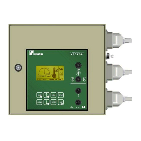
- Page 2 Service Manual START SCREEN: Control status Oil cooler "On" PTO Speed System is running Hydraulic oil temperature Start up control unit Start Control switches not in neutral position Off? Emergency stop STOP! activated Entry expected x1000 Modes of operation 1350 62˚C Remote mode Menu: [ENTER]=ON...
-
Page 3: Table Of Contents
Service Manual PART 1 SCHWING control system 'VECTOR' OPERATION The present instructions are intended to serve as a 'memory aid'. They do not refer to any particular type of machine and do not relieve the user of familiarizing himself with the operating manual of the machine in question. -
Page 4: Commissioning
Service Manual Part 1 Operation • Select the desired mode of operation with the switch in the lower right corner of the vector cover. Commissioning The electrical machine control system can only be activated if the drive configuration has been properly selected: •... -
Page 5: Selecting Local Control
1500 62˚C Menu: [ENTER]=ON Figure 4 Vector display window This symbol is displayed in section #2 of Figure 4 This symbol flashes in section 1 of Figure 4 when the when local control is selected. system is ready for start-up. -
Page 6: Selecting Remote Control
Service Manual Selecting remote control vectorremote.eps Figure 5 Local/remote/ram change switch in “remote” mode x1000 1500 62˚C Menu: [ENTER]=ON remotebox.eps Figure 6 Display screen for remote control This symbol is displayed in section 2 of This symbol flashes in section 1 (Figure the screen (Figure 6). -
Page 7: Selecting Ram Change Mode
Unlock all E-stops. “ ” switch estop.eps panelID.eps Figure 8 This symbol flashes in section 1 (Figure Vector control panel 6) when the system is ready for start-up. Start Start Istart.eps Start up the controller with the “I” switch in (Figure 8). -
Page 8: Emergency Stop Buttons
Service Manual Emergency stop buttons BY-PASS NORM. BY-PASS E_Stopbutton.eps Figure 10 E-stop button by-pass2.eps When an E-stop is pushed, all hydraulic functions of If the problem is actually a bad solenoid, the pilot the machine will stop. Do not use the emergency stop signal to the dump valve can be overridden by having button as an on/off switch. -
Page 9: Options Box
Figure 12 Electrical options box for Vector units h u t o f f w t c h . e p Night light switch The switch shown in Figure 13 is used to activate the optional night light kit. -
Page 10: Control And Monitoring Components
Service Manual Control and monitoring components On start-up, the following data is displayed on screen (Figure 17): Controller cabinet (Figure 16) 1. PTO speed 2. Hydraulic oil temperature 3. Oil cooler “ON” 4. Control status 5. Selected mode of operation 6. -
Page 11: Menu Control
Service Manual Menu control Fast selection/abbreviated function keys (shortcuts): Basic functions of the keys (Figure 18) Press the following keys at the same time: HOME home.eps o w n . e p s O M E E L P T A R T •... -
Page 12: Local Control
Service Manual Local control RPM engine Compressor = down = up Concrete pump delivery rate Vehicle engine = decrease = increase = stop = start Agitator Work light (R) = reverse (suction) = off = on Agitator Water pump (P) = forwards (pumping) (T)= momentary (special control) = off (I) = locked (continuous) -
Page 13: Remote Control
Service Manual Remote control RPM engine Water pump = down = up Agitator in: ( ) = forward Vehicle engine ( ) = reverse = off (stopping) = on (starting) Concrete pump forwards (pumping) Control on Diagnostic horn signal confirm Concrete pump (shut-off) reverse (suction) -
Page 14: Menu Overview - Main Menu
Service Manual Menu overview - Main menu E-Stop Chain Oil Temp. Hydr. 84˚C Diesel Engine Dump Valve BOOM Dump Valve CP Dump Valve MPS Output x1000 x1000 1500 PTO 1500 Function: Function: Menu: [ENTER]=Ein E-Stop Oilcooler Status-Screen? CP Hydraulic Engine Active :Radio Outrigger Station... - Page 15 Service Manual Menu overview - Main menu (continued) Status-Screen? Pumped Volume Counter Start Pumped on the job: 2.4 cbm x1000 PTO 1500 Reset ? - > [START] Pumped Volume Pumped Volume? Malfunction List Start x1000 PTO 1500 Malfunct.List? Malfunct.List! Oil Pressure CP 69.8 Oil Temperature ˚C...
- Page 16 Service Manual Menu overview - Main menu (continued) Oper.Data? Dig. Input? x1000 NA 1350 U/min I/O-Readout? -- Silent Diagnostic ?-- Current: ------------------------ Change? [ENTER] x1000 x1000 Select Y/N [ ] [ ] NA 1350 U/min NA 1350 U/min Store? [ENTER] Parameters? Silent Diagn? Silent Diagn!
- Page 17 Service Manual Menu overview - Main menu (continued) I/O-Readout? x1000 NA 1350 U/min DI11 F31 Pwr Supply Dig Out PO41 Slew right DI12 F32 Pwr Supply PropOut PO42 Slew left Dig. Input? DI13 F20 Pwr Supply Dig Out PO43 Boom A extend DI14 F18 Pwr Supply Inputs PO44...
-
Page 18: Menu Overview - Submenus
Service Manual Menu overview - Submenus Fault list? Oper. data? I/O readout? Parameters? Status Screen? Pumped Volume? E-stop pumping Malfunction list oil parame- digital input? silent volume counter ters diagnostic - DI11-DI58 remote con- trol operating digital output? language hours: boom - DO11-DO38 MMI? -
Page 19: Menu Operation - Example
Service Manual Menu operation - Example RESETTING THE CONCRETE PUMP DAILY DELIVERY RATE ACTION: RESULT: menu line on opening screen: Press: • • • • • • • • • • Menu: [ENTER] = ON next menu line: Press: • • • • • • • • Status Screens? • E• • C• • next menu line: Press: •... -
Page 20: Diagnostic System/ "Fault Handling
Service Manual Diagnostic system/ “Fault handling” The following message origins are available The integrated diagnostic system informs the column): operator about certain operating states, displays faults, and indicates the possible causes. B = Boom (placing boom control) The corresponding messages are displayed on D = Diesel engine (truck diesel engine) the screen of the control unit 1 (Fig. - Page 21 Service Manual Display language Text messages, as well as international symbols, Texts can be displayed in three languages; may include additional information for service English, German, and Spanish. personnel. The language of text displays can be selected in the "Parameter?" menu under "Language Example 1: Text display MMI?".
-
Page 22: Acknowledging Faults
After a fault message has been canceled, it will not be repeated. Schwing assumes no liability for damage caused by faults that have not been rectified. When a low-level fault is reported, this does not mean that it can be ignored completely, only that the job can be finished with... - Page 23 Service Manual Silent diagnostic Silent P a r a m e t e r ? n t h e a f a i s s i g a l l t h e h e t h e E M O T E l c a i t h e t h e h...
- Page 24 Service Manual Reporting and acknowledging faults The way faults are acknowledged depends on t 2. Mode of operation : LOCAL lected mode of operation (LOCAL or REMOTE) and on the s everity of the fault: Silent diagnostic : Yes or No 1.
- Page 25 Service Manual 3. Mode of operation REMOTE Silent diagnostic : No Minor fault The fault is displayed on the screen and a n- nounced by a horn signal. - Activate "QUIT" on the remote Important: control box (Fig. 1) once. Minor faults acknowledged immediately with the "QUIT"...
- Page 26 Service Manual 4. Mode of operation : R E MOTE Silent diagnostic : Yes Minor fault T he fault is displayed on the screen and a n- nounced by the buzzer in the control cabinet. Important: - Activate "QUIT" on the remote control bo x (F ig.
- Page 27 Service Manual 5. Mode of operation : REMOTE Silent diagnos : No Severe fault The fault is displayed on the screen and a n- Important: nounced by the horns. High-level faults can only be acknowl- In addition, the control system goes to e-stop edged with the "QUIT"...
- Page 28 ENTER QUIT • Depress the "QUIT" key on the control cabinet (Fig. 2). Fig. 2 QUIT key VECTOR REMOTE DATA ABBREVIATIONS The fault message is definitely acknowledged. NO DATA SEND HYD. PRESSURE IN BAR The message is deleted from PTO RPM (all digits are numbers)
- Page 29 Service Manual Acknowledging several faults ACKNOWLEDGING SEVERAL FAULTS If several messages are existing, a symbol appears in the lower right- hand corner of the display: – Acknowledge the first message as usual. The next message appears and the buzzer sounds. –...
-
Page 30: Summary Of Messages
Service Manual Summary of messages Code international version (symbolic) plain text messages B = Boom Limitation Slewing Gear B01M Activated ! BOOM Limitation Activated ! B02M Disconnected / Overload E-Stop Solenoid BOOM ! B04L Disconnected / Overload Solenoid Slewing Right PO41 - PO41 ! B05L... - Page 31 Service Manual Disconnected / Overload Solenoid BOOM B retract PO46 - PO46 ! B10L Disconnected / Overload Solenoid BOOM C extend PO47 - PO47 ! B11L Disconnected / Overload Solenoid BOOM C retract PO48 - PO48 ! B12L Disconnected / Overload Solenoid BOOM D extend PO51 - PO51 !
- Page 32 Service Manual PTO RPM-Limit exceeded ! D04L Indicator-Switch PTO = ON/OFF Fault ! D05L Indicator-Signal Engine Load Fault ! D06L Indicator Lvel Diesel-Reservoir Fault ! D07L Disconnected Truck Interface DO31 Diesel Start - D031 ! D08L Overload Truck Interface DO31 Diesel Start - D031 ! D09L Disconnected...
- Page 33 Service Manual ! Machine Safety Stop ! High Truck Coolant Temperature ! D16H ! Machine Safety Stop ! Low Truck Oil Pressure ! D17H ! Machine Safety Stop ! Low Level Hydraulic Oil ! D18H ! Machine Safety Stop ! Battery charging On Truck Fault ! D19H...
- Page 34 Service Manual Level Transmitter Hydraulic Reservoir Fault ! M08L Transmitter Oil Pressure Service Fault ! M09L Transmitter Cleaning Ball Detection Fault ! M10L Disconnected PowerOutput DO13 Oil Cooler - DO13 ! M11L Overload / Fuse PowerOutput DO13 Oil Cooler - DO13 ! M12L Disconnected PowerOutput DO12...
- Page 35 Service Manual Overload Solenoid Ball-Injector DO38 - DO38 ! M20L Disconnected Solenoid DO26 Water Pump - DO26 ! M21L Overload Solenoid DO26 Water Pump - DO26 ! M22L Kabelbruch Schaltventil Kompressor - DO28 ! DO28 M23L Disconnected Solenoid DO28 Air-Compressor - DO28 ! M24L Disconnected Solenoid Agitator...
- Page 36 Service Manual Overload Solenoid High Pressure DO27 Water Pump - DO27 ! M32L Disconnected Solenoid End-Hose Shut-Off DO37 - DO37 ! M33L Overload Solenoid End-Hose Shut-Off DO37 - DO37 ! M34L Disconnected / Overload Solenoid Hydraulic On PO56 Outrigger - PO56 ! M35L ! Machine Safety Stop ! Hydraulic Oil...
- Page 37 Service Manual P = Pump Pressure Limiter Concrete Pump Activated ! P01M Stroke Rate Limitation Concrete Pump Activated ! P02M Hopper Grate Open ! P03M Low Level Water Reservoir ! P04M Oil Temperature High, Power Limiter Concrete Pump Activated ! P05L Transmitter Oil Pressure Concrete...
- Page 38 Service Manual Disconnected Solenoid Concrete Pump DO24 Reverse - DO24 ! P12L Overload Solenoid Concrete Pump DO24 Reverse - DO24 ! P13L Disconnected / Overload Solenoid Stroke Limiter PO55 - PO55 ! P14L R = Remote R01M Emergency-Stop On Radio Control Box Activated ! R02M Low Battery In Radio...
- Page 39 Service Manual Radio Control Signal With Faulty Address Received ! R09L Disconnected Boom Release Solenoid ! R10L Overload Boom Release Solenoid ! R11L ! Machine Safety Stop ! Hydraulic Enable Fault! R12H S = System Disconnected Rear Panel ! S01M Power Supply MAIN-Board Fault !
- Page 40 Service Manual Fuse F 20 Fault ! F 20 S07L Fuse F 16 Fault ! F 16 S08L Fuse F 31 Fault ! F 31 S09L Fuse F 32 Fault ! F 32 S10L MF1 : Power Supply Diagnosis E-Stop Board DI15 - DI18 Fault ! S11L MF2 : Power Supply...
- Page 41 Service Manual Reference Voltage for analog Sensors AI12, AI13,AI14,AI16 Fault ! S19L Multi Fuse MMI-Board Fault ! S20L ECTOR ONTROLLER ERVICE ANUAL...
- Page 42 3. Push the ENTER button to select yes. The • Be sure of unit's stability controller will then restore the parameters to the values set in the Schwing Test Department. After about 10 seconds, the system will reset itself. NOTE! When the system restart screen appears Heat the oil first...
- Page 43 “I” switch on the remote box. the teach mode. Switch the local/remote 2. Open the front cover of the Vector controller, and switch to the remote position, and activate plug in the hardware “Teach Key” to the connector the “I”...
- Page 44 Service Manual 5. After activating the “I” switch, the display window 7. Start by holding down the “I” switch on the remote will show you the screen in Figure 23. This chart box while you activate the right hand joystick shows you RPM, oil temperature, a picture of a forward to the extend positon.
- Page 45 Service Manual 9. If the boom is not moving, you should increase the 11. If you felt that the boom took off too fast when the percentage to this function by activating the joystick was activated and the percentage needs to throttle switch (Figure 27) to the “+”...
- Page 46 Service Manual 1760 rpm 52 ˚C Teach mode! Teach Mode maxparameterscreen.eps Figure 32 MAX parameter screen 16. The handle on the boom valve should now have Figure 31 moved to the full extend position. Grab the handle Manual boom control handles and pull or push it in the same direction it has already moved.
- Page 47 Service Manual 18. The procedure is the same for all functions, so 1760 rpm 52 ˚C activate the “I” switch and move to the next function until you have completed all parameter settings. Any time you have entered information Teach and then change the position of the local/remote switch, the controller will first ask if you want to mode!
- Page 48 The restart takes only seconds, and when completed the display will again show the screen below (Figure 37). Start x1000 1760 52˚C Menu: [ENTER]=ON vectornormal.eps Figure 37 Vector normal operation screen ECTOR ONTROLLER ERVICE ANUAL...
- Page 49 Service Manual PART 3 SCHWING control system 'VECTOR' EASy MODE Short Instructions Operational Components Switches LCD Screen Normal setup now? EAsy will be deactivated Please confirm with 'OFF' switch! Or select left or right working area! EASy Assistant HOME HELP START “START”...
- Page 50 Service Manual Activating full outrigger Step 2 extension setup The system is waiting for a command. Step 1 Normal setup now? Put the “working area selection switch” to the center EASy will be deactivated position. Please confirm with 'OFF' switch! Or select left or right working area! EASy Assistant...
- Page 51 Service Manual EASy Assistant: Operating one Step 1b side only Push the “START“button to confirm left side setup. Step 1 “START” Button Put the “working area selection switch“to the desired position. (in this case left.) HELP START ENTER QUIT Figure 45 “START Button”...
- Page 52 For roll & fold™ units There are no further steps. The system recognizes that boom #1 is vertical but the operator must now confirm that #2 is vertical as well. The assistant is finished now and the Display shows the normal Vector screen. Are boom #1 & #2 vertical? Start ->...
- Page 53 Figure 51 Figure 53 “Rotate boom to working area” screen Vector normal operation screen Slewing to the opposite side of the selected working area has been disabled. Step 4b The system has recognized that the boom is now in the selected working area.
- Page 54 Service Manual Functional limitation of boom slewing Functional limitation of main boom During operation boom slewing is restricted to the During operation the main boom is restricted from selected working area. going beyond 90 degrees. Figure 54 Figure 55 Slewing limitation Boom limitation Maximum slewing speed is automatically reduced Maximum speed for boom #1 retract is automatically...
- Page 55 Do you want to stow the boom now? EASy Assistant Please confirm with Figure 58 Start -> [START] Vector normal operation screen EASy Assistant Figure 56 “Stow the boom” screen Push the “START“button to confirm that S TAR T both booms are vertical t a r t .
- Page 56 Service Manual Step 3 Step4 The system recognizes when the zero position has been After pushing the “START“button the operator should reached and you may now lower the boom to the travel select the center position of the “working area selection position.
Need help?
Do you have a question about the VECTOR and is the answer not in the manual?
Questions and answers
Need fuse panel inside vector box with fuse assignment
The fuse panel layout and fuse assignments for the Schwing VECTOR include the following:
- MF6 Fault: Related to S16L
- MF7 Fault: Power Supply RAM-Change Station, DI51–DI54 (S17L)
- MF8 Fault: Power Supply DI55–DI58 (S18L)
- Multi Fuse MMI-Board Fault: S20L
These indicate that each fuse (MF6, MF7, MF8, etc.) is linked to specific digital inputs or power supply functions. The S16L–S20L designations likely represent the physical fuse positions or identifiers on the fuse panel.
This answer is automatically generated
La toma de fuerza solo revoluciona has 1500 no llega a los 1760 rpm ¿¿¿como hago para subirlo las rpm ha 1760