Table of Contents
Advertisement
05. 2004
05. 2004
SCHWING ñ Control system " VECTOR "
SCHWING ñ Control system " VECTOR "
valid from software version V 1.10 onwards
valid from software version V 1.10 onwards
P P A A R R T T 1 1 : : O O P P E E R R A A T T I I O O N N
P P A A R R T T 2 2 : : T T E E A A C C H H M M O O D D E E
Publis
Pub
lished by:
hed by: SC
SCHW
HWIN
ING Gm
Dept.:
Dept.:
VVW
VVW
Postfach : 20 03 62
Postfach : 20 03 62
D - 44647 Herne
D - 44647 Herne
Id. no.: 10207417
Id. no.: 10207417
15.04.04 13:06
15.04.04 13:06
All righ ts reserv
All righ
ts reserv ed. Repro
ed. Repro ducti
SERVICE MANUAL
SERVICE MANUAL
1
1
2
2
x1000
x1000
0
0
3
3
PTO
PTO
1500
15
00
rpm
rpm
Menu:
Menu:
[ENTER
[ENTER
H
H
O
O
M
M
E
E
+
+
C
C
L
L
E
E
A
A
R
R
-
-
G GmbH
bH
ducti on - in whole or in par
on - in whole or in par t - only with th
OK
OK
OFF
OFF
62˚C
62˚C
]=ON
]=ON
H
H
E
E
L
L
P
P
START
START
E
E
N
N
T
T
E
E
R
R
QUIT
QUIT
t - only with th e express w
e express w ritten pe
004.103.01-en
004.103.01-en
ritten pe rmissi
rmissi on of SCHW
on of SCHW ING GmbH
ING GmbH . .
Advertisement
Table of Contents

Related Manuals for Schwing VECTOR

Summary of Contents for Schwing VECTOR
- Page 1 05. 2004 05. 2004 SCHWING ñ Control system " VECTOR " SCHWING ñ Control system " VECTOR " SERVICE MANUAL SERVICE MANUAL valid from software version V 1.10 onwards valid from software version V 1.10 onwards x1000 x1000 1500 rpm ...
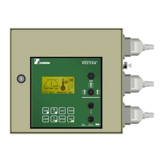
- Page 2 START SCREEN: START SCREEN: Control status Control status Oil cooler "On" Oil cooler "On" PTO Speed PTO Speed OK OK System is running System is running Hydraulic oil temperature Hydraulic oil temperature Start up control unit Start up control unit Start Start Control switches not...
- Page 3 START SCREEN: START SCREEN: Control status Control status Oil cooler "On" Oil cooler "On" PTO Speed PTO Speed OK OK System is running System is running Hydraulic oil temperature Hydraulic oil temperature Start up control unit Start up control unit Start Start Control switches not...
- Page 4 PART 1 PART 1 - 1 - - 1 - SCHWING control SCHWING control system 'VECTOR' system 'VECTOR' OPERATION OPERATION The present instructions are intended to serve as a 'memory aid'. They do not refer to any The present instructions are intended to serve as a 'memory aid'. They do not refer to any...
- Page 5 PART 1 PART 1 - 2 - - 2 - 1. CO COMM MMIS ISSI SIONI ONING Now, the following functions can be Now, the following functions can be activated: activated: - - s s i i g g n n a a l h l ho o r r n o n on n The electrical machine control system can only...
- Page 6 62˚C Menu: [ENTER]=ON HOME HELP START CLEAR ENTER QUIT Fig. 3 All righ ts reserv ed. Reproduction - in whole or in par t - only with th e express w ritten pe rmissi on of SCHWING GmbH. 004.104.01-en...
- Page 7 4 (Fig. All rights reser ved. Reproduction - in whole or i n part - only wit h the expres s written p ermission of SCHWING GmbH. 004.104.01-en...
- Page 8 (Fig. 3). See machine operating instructions, chapter 4.43: 'RAM CHANGE MODE'. Fig. 3 All righ ts reserv ed. Reproduction - in whole or in par t - only with th e express w ritten pe rmissi on of SCHWING GmbH. 004.104.01-en...
- Page 9 In normal operating conditions always stop the machine functions and the engine with the con- trols provided for this purpose. All rights reserved. Reproduction - in whole or i n part - only wit h the expres s written p ermission of SCHWING GmbH. 004.104.01-en...
- Page 10 Stop working on the job and have the emer- gency shut-off system be repaired immedi- ately. All rights reserv ed. Reproduction - in whole or in par t - only with th e express w ritten permissi on of SCHWING GmbH. 004.104.01-en...
- Page 11 5 - Selected mode of operation 6 - Concrete pump delivery rate 7 - Menu options All rights reser ved. Reproduction - in whole or i n part - only wit h the expres s written p ermission of SCHWING GmbH. 004.104.01-en...
- Page 12 Starting not possible: switches not in neutral position. Fig. 1 Starting not possible: emergency stop activated All righ ts reserv ed. Reproduction - in whole or in par t - only with th e express w ritten pe rmissi on of SCHWING GmbH. 004.104.01-en...
- Page 13 Execution of certain actions, e.g. re- setting of the concrete pump's deli- very rate counter. All rights reser ved. Reproduction - in whole or i n part - only wit h the expres s written p ermission of SCHWING GmbH. 004.104.01-en...
- Page 14 (I) = locked (continuous) (T)= momentary (special control) Vibrator Ball injection system High-pressure water pump All righ ts reserv ed. Reproduction - in whole or in par t - only with th e express w ritten pe rmissi on of SCHWING GmbH. 004.104.01-en...
- Page 15 = transmitting control signals = increase = reduce Vibrator in automatic mode on All rights reser ved. Reproduction - in whole or i n part - only wit h the expres s written p ermission of SCHWING GmbH. 004.104.01-en...
- Page 16 PART 1 - 13a - 4.1 MENU OVERVIEW - MAIN MENU Pumped Volume Counter E-Stop Chain Dump Valve BOOM Start Pumped on the job: Dump Valve CP 2.4 cbm Dump Valve MPS x1000 x1000 x1000 PTO 15 0 0 r pm Reset ? - >...
- Page 17 PART 1 - 13b - x1000 x1000 NA 135 0 U/min NA 1350 U/min DI11 F31 Pwr Supply Dig Out DI12 F32 Pwr Supply PropOut I/O-Readout? Dig. Input? DI13 F20 Pwr Supply Dig Out DI14 F18 Pwr Supply Inputs DI15 Dump Valve Boom ...
- Page 18 - boom system clock - slew drive - stabilizers All rights reser ved. Reproduction - in whole or i n part - only wit h the expres s written p ermission of SCHWING GmbH. 004.104.01-en...
- Page 19 18,0 m³ Press: daily pumping rate reset to 0.0 m³ Press: return to opening screen All righ ts reserv ed. Reproduction - in whole or in par t - only with the ex press written perm ission of SCHWING GmbH. 004.104.01-en...
- Page 20 PART 1 - 16 - All righ ts reserv ed. Reproduction - in whole or in part - onl y with the exp ress written perm ission of SCHWIN G GmbH. 004.104.01-en...
- Page 21 PART 1 - 17 - 6. DIAGNOSTIC SYSTEM / "FAULT HANDLING" (from software version V 1.10 onwards) The following message origins are available The integrated diagnosis system informs the column): operator about certain operating states, displays faults and indicates the possible causes. B = Boom (placing boom control) The corresponding messages are displayed on D = Diesel engine (truck diesel engine)
- Page 22 PART 1 - 18 - DISPLAY LANGUAGE Texts can be displayed in three languages. Text messages as well as international symbols may include additional information for service The language of text displays can be selected in personnel. the "Parameter?" menu under "Language Example 1: Text display MMI?".
- Page 23 They are announced only visully on ATTENTION: display and can be acknowledged RISK OF ACCIDENT AND DAMAGE with the "CLEAR" key. SCHWING assumes no liability for damage caused by faults not recti- fied. ACKNOWLEDGING FAULTS When a "low level fault" is reported,...
- Page 24 PART 1 - 20 - SILENT DIAGNOSTIC In the "Parameter?" menu under "Silent diag?" the operator can select whether a fault is signalled in the "REMOTE" mode of operation by the horn or the buzzer in the control cabinet. MENU OVERVIEW – Silent diagnostic Display menu line / Key: ...
- Page 25 Part 1 - 21 - REPORTING AND ACKNOWLEDGING OF FAULTS Faults are acknowledged dependent on the se- 2. Mode of operation : LOCAL lected mode of operation (LOCAL or REMOTE) and on the severity of the fault: Silent diagnostic : Yes or No 1.
- Page 26 Part 1 - 22 - 3. Mode of operation : LOCAL Silent diagnostic : No Low level fault The fault is displayed on the screen and a n- nounced by a horn signal. - Activate "QUIT" on the remote Important: control box (Fig.
- Page 27 Part 1 - 23 - 4. Mode of operation : REMOTE Quiet diagnosis : Yes Low level The fault is displayed on the screen and a n- nounced by the buzzer in the control cabinet. Important: - Activate "QUIT" on the remote control box (Fig.
- Page 28 Part 1 - 24 - 5. Mode of operation : REMOTE Quiet diagnosis : No High level The fault is displayed on the screen and a n- Important: nounced by the horns. High levelfaults can only be acknowl- edged with the "QUIT" key on the In addition, the control system is switched off.
- Page 29 Part 1 - 25 - 6. Mode of operation : REMOTE Silent diagnostic : Yes High level fault The fault is displayed on the screen and a n- Important: nounced by the buzzer in the control cabinet High levelfaults can only be acknowl- edged with the "QUIT"...
- Page 30 Part 1 - 26 - ACKNOWLEDGING OF SEVERAL FAULTS If several messages are existing, a symbol appears in the lower right- hand corner of the display: – Acknowledge the first message as usual. The next message appears and the buzzer sounds. –...
- Page 31 PART 1 - 27 - 6.1 SUMMARY OF MESSAGES Code international version (symbolic) plain text messages B = Boom Limitation Slewing Gear B01M Activated ! BOOM Limitation Activated ! B02M Disconnected / Overload E-Stop Solenoid BOOM ! B04L Disconnected / Overload Solenoid Slewing Right PO41 - PO41 !
- Page 32 Power Limitation Diesel Engine Activated ! D02M PTO is not working or Prox-Switch PTO-RPM Fault ! D03L All righ ts reserved. Reproduction - in whole or in par t - only with the ex press written permission of SCHWING GmbH. 004.138.00-en...
- Page 33 PART 1 - 29 - PTO RPM-Limit exceeded ! D04L Indicator-Switch PTO = ON/OFF Fault ! D05L Indicator-Signal Engine Load Fault ! D06L Indicator Lvel Diesel-Reservoir Fault ! D07L Disconnected Truck Interface DO31 Diesel Start - D031 ! D08L Overload Truck Interface DO31 Diesel Start - D031 !
- Page 34 Please Exchange Filter! M05L Low Level Hydraulic Oil Reservoir ! M06L High Temperature Air Compressor ! M07L All righ ts reserved. Reproduction - in whole or in par t - only with the ex press written permission of SCHWING GmbH. 004.138.00-en...
- Page 35 PART 1 - 31 - Level Transmitter Hydraulic Reservoir Fault ! M08L Transmitter Oil Pressure Service Fault ! M09L Transmitter Cleaning Ball Detection Fault ! M10L Disconnected PowerOutput DO13 Oil Cooler - DO13 ! M11L Overload / Fuse PowerOutput DO13 Oil Cooler - DO13 ! M12L Disconnected PowerOutput...
- Page 36 DO25 - DO25 ! M30L Disconnected Solenoid High Pressure DO27 Water Pump - DO27 ! M31L All righ ts reserved. Reproduction - in whole or in par t - only with the ex press written permission of SCHWING GmbH. 004.138.00-en...
- Page 37 PART 1 - 33 - Overload Solenoid High Pressure DO27 Water Pump - DO27 ! M32L Disconnected Solenoid End-Hose Shut-Off DO37 - DO37 ! M33L Overload Solenoid End-Hose Shut-Off DO37 - DO37 ! M34L Disconnected / Overload Solenoid Hydraulic On PO56 Outrigger - PO56 ! M35L...
- Page 38 DO23 Forward - DO23 ! P10L Overload Solenoid Concrete Pump DO23 Forward - DO23 ! P11L All righ ts reserved. Reproduction - in whole or in par t - only with the ex press written permission of SCHWING GmbH. 004.138.00-en...
- Page 39 PART 1 - 35 - Disconnected Solenoid Concrete Pump DO24 Reverse - DO24 ! P12L Overload Solenoid Concrete Pump DO24 Reverse - DO24 ! P13L Disconnected / Overload Solenoid Stroke Limiter PO55 - PO55 ! P14L R = Remote R01M Emergency-Stop On Radio Control Box Activated !
- Page 40 K 13 K 13 Override / Fault ! S05L Fuse F 18 Fault ! F 18 S06L All righ ts reserved. Reproduction - in whole or in par t - only with the ex press written permission of SCHWING GmbH. 004.138.00-en...
- Page 41 PART 1 - 37 - Fuse F 20 Fault ! F 20 S07L Fuse F 16 Fault ! F 16 S08L Fuse F 31 Fault ! F 31 S09L Fuse F 32 Fault ! F 32 S10L MF1 : Power Supply Diagnosis E-Stop Board DI15 - DI18 Fault ! S11L...
- Page 42 Reference Voltage for analog Sensors AI12, AI13,AI14,AI16 Fault ! S19L Multi Fuse MMI-Board Fault ! S20L All righ ts reserved. Reproduction - in whole or in par t - only with the ex press written permission of SCHWING GmbH. 004.138.00-en...
- Page 43 The activities described in the present summarized instructions may only be performed by specially trained persons having demonstrated their ability to do such work. SCHWING does not assume any liability for damage resulting from inappropriate attempts to perform machine adjustments.
- Page 44 Attention: the key isgoing in to the connector, one way. Fig. 3 Fig. 1 All rights reser ved. Reproduction - in whole o r in part - only wit h the expres s written permission of SCHWING GmbH. 004.105.01-en...
- Page 45 PART 2 - 3 - Screen (Fig. 1) is displayed and START is flashing. Start Start the control with the pushbut- Teach ton on the remote-control trans- x1000 mode! mitter. 1760 rpm 62˚C Successful starting is confirmed Menu: [ENTER]=ON by a brief acoustic signal and the 'OK"...
- Page 46 Retracting boom section 1 (A), MAX value (rabbit) 1760 rpm 62 ˚C Teach mode! Teach Mode Fig. 2 All rights reserved. Reproduction - in whole o r in part - only wit h the expres s written permission of SCHWING GmbH. 004.105.01-en...
- Page 47 PART 2 - 5 - Change the value within the preset ñ When all values are OK, end the limits by depressing the RPM teach mode by switching over switch: from remote-control to (+) = up local control or to (-) = down piston replacement When either limit is reached, the...
- Page 48 1500 rpm 62˚C Menu: [ENTER]=ON Fig. 4 HOME HELP START CLEAR ENTER QUIT Fig. 1 All rights reser ved. Reproduction - in whole o r in part - only wit h the expres s written permission of SCHWING GmbH. 004.105.01-en...
Need help?
Do you have a question about the VECTOR and is the answer not in the manual?
Questions and answers