Table of Contents
Advertisement
Quick Links
Non-Linear Systems
PM-452
DIGITAL PANEL METERS
INTRODUCTION
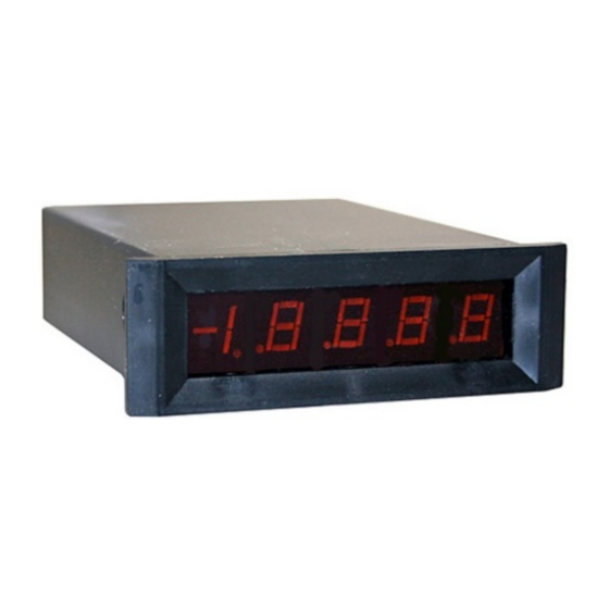
The Model PM-452 is a highly accurate, four and
one-half digit, fixed range, miniature digital panel
meter with automatic polarity indication for making
DC voltage measurements. DC current can also be
measured using external shunt resistors. The
instrument is available in any one of four ranges:
2V, 20V, 200V or 1000V F.S.
System accommodations include multiplexed BCD
outputs, a busy/done output and a hold input. The
instrument also has display enable and polarity
enable capabilities.
Modification from any one range to another is easily
accomplished by changing one or two resistors.
is
accomplished
potentiometer accessible at the rear panel.
The PM-452 has a 0.3 inch high LED numeric
readout. The readout also includes LED + and -
polarity signs and decimal points for each decade.
An active filter at the signal input provides high
normal -mode refection.
For operation, an external +5VDC ±5% power
supply is required. See figure 1 for a typical power
supply circuit.
Figure 1: Power Supply Schematic
SPECIFICATIONS
RANGE:
0 to 2 Volts
0 to 20 Volts
0 to 200 Volts
0 to 1000 Volts
ACCURACY: ±0.02% F.S. (23° C ±2°)
SPEED:
3 Rdg/Sec, nominally
OPERATING TEMP: 0° C to +50° C
POWER: +5 VDC ±5% @ 140 mA, max.
DISPLAY:
TURN ON TIME:
TEMPERATURE COEFFICIENT:
±(0.01% Rdg + 0.001% F.S.)/°C
INPUT Z:
METHOD of A to D CONVERSION:
SETTLING TIME:
COMMON-MODE VOLTAGE:
SIGNAL LO may be anywhere in the range from
-0.1V to +1V with respect to power supply
common. Note that if the power for the meter is
supplied from an isolated power supply, the
effective common-mode voltage is the isolation
voltage rating of the power supply.
COMMON-MODE REJECTION:
NORMAL-MODE REJECTION
typical, 40 dB minimum @ 50-60 Hz
INPUT CURRENT:
DECIMAL LOCATION:
by
adjusting
a
May be positioned by a jumper to any of four
locations,
INPUT VOLTAGE PROTECTION:
±100 VDC or peak VAC, 2V range; ±350 VDC or
peak VAC, 20V range; ±1000 VDC or peak VAC,
200V and 1000V ranges.
OVERLOAD INDICATION:
except the 1000v range, an input exceeding full
scale is displayed as four flashing zeros.
WEIGHT: Approximately 3 ounces
INSTALLATION
1
. Mount the PM-452 as follows:
a. Cut a hole in panel (Figure 2).
b. Slide trim plate over meter housing, facing
beveled edge of trim plate forward.
c. Insert meter through opening in panel form
front of panel.
d. Fit mounting clips (2) into slots at sides of
instrument. Foot of clip should face forward.
e. Thread screws (2) into clips and tighten screw
against rear surface of panel.
2. The optional connector should be NLS part
number 39-195, or equivalent. See Figure 3 for
connector pin information.
LED, red, 0.3" high
10 seconds to ±
0.05%
accuracy
2V range, 1000 MΩ; 20V range, 1 MΩ
; 200V and 1000V
ranges, 10 MΩ
Dual slope
2 seconds, including
polarity change
80 dB, min.
: 60 dB
250 pA, maximum
X . X . X . X . X
On all ranges
Panel Thickness 1/16" to
Center Line
Panel Cutout
Center Line
w ithout Trim
w /Trim Plate
w /Trim Plate
Plate
A
2 17/32
B
31/32
C
15/16
1 3/16 min
D
3 1/8 min
3 1/8 min
E
Figure 2. Outline Drawing
OPERATION
POWER AND SIGNAL CONNECTIONS
1. Connect power supply common to pins K and L
on the edge connector.
2. Connect +5VDC power to pin 9.
3. Connect the DC voltage to be measured to pin 5
and H of the connector (SIGNAL HI to pin H and
SIGNAL LO to pin 5).
NOTE:
In an electrically noisy environment it may be
desirable to use a shielded lead for this
connection. If a shielded lead is used, the
shield should be connected to SIGNAL LO of
the DC voltage to be measured.
4. Connect the negative terminal of the power
supply to SIGNAL LO of the DC voltage to be
measured. For maximum accuracy and stability,
this connection should be made at the source
and not on the connector.
5. Polarity is enabled from factory. To remove the
polarity sign, remove R2 (see figure 4).
6. Connect pin 8, display enable, to pin 9 (+5VDC).
7. Decimal Point indication if desired is connected
from pin 1 (Decimal Common) to pin A, B, C or D
depending upon which decimal point is to be
illuminated.
Decimal Location:
X . X . X . X . X
Connector Pin:
D C B
If decimal point is not desired, omit the jumper.
¼"
Cutout For Multiple
Mounting w ithout Trim
Plate
Number of units x 15/16
A
Advertisement
Table of Contents

Related Manuals for NLS PM-452


Summary of Contents for NLS PM-452
- Page 1 INTRODUCTION COMMON-MODE VOLTAGE: SIGNAL LO may be anywhere in the range from The Model PM-452 is a highly accurate, four and -0.1V to +1V with respect to power supply one-half digit, fixed range, miniature digital panel common. Note that if the power for the meter is...
- Page 2 Due to the solid-state construction and 100% F, respectively. When digit 5 enable (pin J) goes to test and calibration of your PM-452 is an a "low" logic level (zero), the 1, 2, 4 and 8 BCD Figure 4. Component Location extremely reliable instrument.
Need help?
Do you have a question about the PM-452 and is the answer not in the manual?
Questions and answers