Table of Contents
Advertisement
Quick Links
Advertisement
Table of Contents

Related Manuals for HHP Scanteam 4800

Summary of Contents for HHP Scanteam 4800
- Page 1 IMAGETEAM™ 4600/4800 Retail /Commercial Area Imager ™...
-
Page 3: Statement Of Agency Compliance
Statement of Agency Compliance This device complies with part 15 of the FCC Rules. Operation is subject to the following two conditions: (1) this device may not cause harmful interference, and (2) this device must accept any interference received, including interference that may cause undesired operation. - Page 4 The CE mark on the product indicates that the system has been tested to and conforms with the provisions noted within the 89/336/ EEC Electromagnetic Compatibility Directive and the 73/23/EEC Low Voltage Directive. Complies with: EN55022:1998 (for ITE emissions) EN55024:1998 (for ITE immunity), including CISPR 22B:1997 EN61000-4-2:1995 EN61000-4-3:1995 For further information please contact:...
- Page 5 Solids and Water Protection The IT4600 has a rating of IP41, immunity of foreign particles and dripping water. The IT4800 has a rating of IP54, immunity of windblown dust penetration and splashing water.
- Page 6 Disclaimer Hand Held Products, Inc., d/b/a HHP (“HHP”) reserves the right to make changes in specifications and other information contained in this document without prior notice, and the reader should in all cases consult HHP to determine whether any such changes have been made. The information in this publication does not represent a commitment on the part of HHP.
-
Page 7: Table Of Contents
Table of Contents Chapter 1 - Getting Started About This Manual ... 1-1 Unpacking the Imager... 1-1 IT4600/4800 Models ... 1-2 IT4600/4800 Imager Identification... 1-3 Connecting the Imager When Powered by Host (Keyboard Wedge)... 1-4 Reading Techniques... 1-5 Plug and Play ... 1-6 Keyboard Wedge... - Page 8 Wand Emulation... 2-14 Data Block Size ... 2-14 Delay Between Blocks... 2-14 Overall Checksum ... 2-15 Wand Emulation Transmission Rate ... 2-15 Wand Emulation Polarity ... 2-16 Wand Emulation Idle... 2-16 Chapter 3 - Output Good Read Indicators... 3-1 Beeper – Good Read... 3-1 Beeper Volume –...
- Page 9 Output Sequence Overview...3-14 Output Sequence Editor ...3-16 Require Output Sequence ...3-16 Multiple Symbols ...3-17 No Read...3-17 Print Weight ...3-18 Video Reverse ...3-18 Working Orientation...3-19 Chapter 4 - Data Editing Prefix/Suffix Overview ...4-1 To Add a Prefix or Suffix: ...4-2 To Clear One or All Prefixes or Suffixes: ...4-3 To Add a Carriage Return Suffix to all Symbologies...4-3 Prefix Selections ...4-4 Suffix Selections ...4-4...
- Page 10 Wand/Laser Emulation Multi Block ... 6-3 Delay Between Blocks... 6-3 Overall Checksum ... 6-3 Wand Emulation Transmission Rate ... 6-4 Wand Emulation Polarity ... 6-4 Wand Emulation Idle... 6-5 Data Block Size ... 6-5 Secondary Laser Emulation ... 6-5 Laser Emulation Transmission Rate ... 6-6 Laser Emulation Polarity...
- Page 11 Interleaved 2 of 5 ...7-10 Check Digit ...7-11 Interleaved 2 of 5 Message Length...7-11 Code 93 ...7-12 Code 93 Message Length...7-12 Code 93 Code Page...7-13 Code 2 of 5 ...7-13 Code 2 of 5 Message Length ...7-13 IATA Code 2 of 5 ...7-14 IATA Code 2 of 5 Message Length...7-14 Matrix 2 of 5 ...7-15 Matrix 2 of 5 Message Length ...7-15...
- Page 12 UPC-A/EAN-13 with Extended Coupon Code ... 7-21 UPC-E0 ... 7-22 UPC-E0... 7-22 UPC-E0 Expand ... 7-22 UPC-E0 Addenda Required... 7-23 UPC-E0 Addenda Separator... 7-23 UPC-E0 Check Digit ... 7-23 UPC-E0 Number System... 7-24 UPC-E0 Addenda ... 7-24 UPC-E1 ... 7-24 EAN/JAN-13 ...
- Page 13 Code 16K ...7-35 Code 16K Message Length...7-35 Code 49 ...7-36 Code 49 Message Length...7-36 PDF417 ...7-37 PDF417 Message Length...7-37 MicroPDF417 ...7-37 MicroPDF417 Message Length ...7-38 EAN•UCC Composite Codes ...7-38 UPC/EAN Version...7-39 EAN•UCC Composite Code Message Length...7-39 EAN•UCC Emulation ...7-40 TCIF Linked Code 39 (TLC39) ...7-40 Postal Codes ...7-41 Postnet...7-41 Planet Code ...7-42...
- Page 14 Chapter 8 - Imaging Commands Image Snap - IMGSNP ... 8-1 IMGSNP Modifiers ... 8-1 Image Ship - IMGSHP ... 8-2 IMGSHP Modifiers ... 8-3 Intelligent Signature Capture - IMGBOX... 8-6 IMGBOX Modifiers ... 8-7 Chapter 9 - OCR Programming OCR Fonts ...
- Page 15 Chapter 11 - Utilities To Add a Test Code I.D. Prefix to All Symbologies ...11-1 Show Software Revision ...11-1 Show Data Format...11-1 Resetting the Standard Product Defaults...11-1 Test Menu...11-2 2D PQA (Print Quality Assessment)...11-2 Visual Menu 2003 ...11-2 Installing Visual Menu 2003 from the Web ...11-3 Quick*View...11-4 Installing Quick*View from the Web...11-4 Chapter 12 - Serial Programming Commands...
- Page 16 Chapter 13 - Product Specifications IT4600 Product Specifications... 13-1 IT4800 Product Specifications... 13-2 Standard Cable Pinouts ... 13-4 Chapter 14 - Maintenance Repairs... 14-1 Maintenance ... 14-1 Cleaning the Imager’s Window... 14-1 Inspecting Cords and Connectors ... 14-1 Replacing the Interface Cable... 14-2 Troubleshooting ...
-
Page 17: Chapter 1 - Getting Started
Getting Started The IMAGETEAM™ 4600 and 4800 mark a new performance level for hand held area imagers. The IT4600/4800 hand held area imagers are powered by HHP’s Adaptus technology. The performance of Adaptus technology delivers aggressive read rates and depths of field on 1D, stacked linear, and matrix codes. -
Page 18: It4600/4800 Models
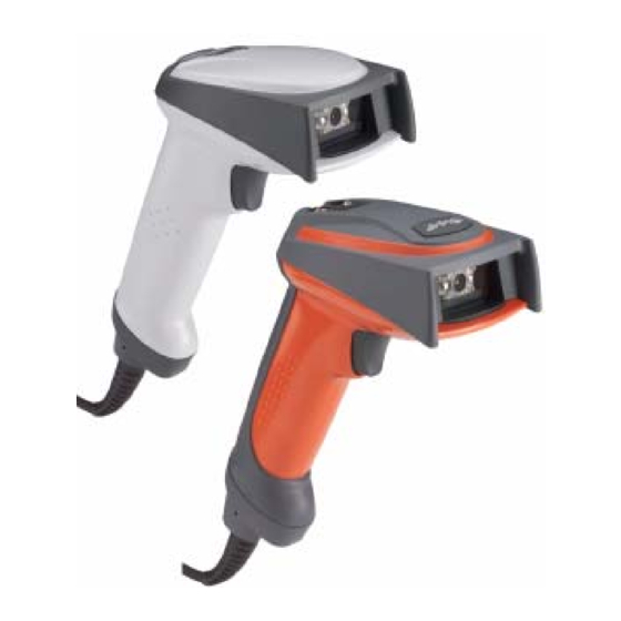
IT4600/4800 Models There are three models of the IT4600/4800 imager, which may be used with many interfaces described in this manual. Refer to the chart below to determine the models that can be used with your interface. The following interfaces apply to all IT4600/4800 focal distances and decoding options. -
Page 19: It4600/4800 Imager Identification
IT4600/4800 Imager Identification IMAGETEAM™ 4600/4800 User’s Guide 1 - 3... -
Page 20: Connecting The Imager When Powered By Host (Keyboard Wedge)
Connecting the Imager When Powered by Host (Keyboard Wedge) A imager can be connected between the keyboard and PC as a “keyboard wedge,” plugged into the serial port, or connected to a portable data terminal in wand emulation or non decoded output mode. The following is an example of a keyboard wedge connection: 1. -
Page 21: Reading Techniques
Reading Techniques The imager has a view finder that projects a bright red or green aiming beam that corresponds to the imager’s horizontal field of view. The aiming beam should be centered over the bar code, but it can be positioned in any direction for a good read. -
Page 22: Plug And Play
Note: This interface applies to the 4600/4800SR050 model. For most laptops, scanning the Laptop Direct Connect bar code allows operation of the scanner in parallel with the integral keyboard. The following Laptop Direct Connect bar code also programs a carriage return (CR) suffix, and... -
Page 23: Rs-232
RS-232 The RS-232 Interface bar code is used when connecting to the serial port of a PC or terminal. The following RS-232 Interface bar code also programs a carriage return (CR) and a line feed (LF) suffix, baud rate, and data format as indicated below: Option Setting... -
Page 24: Ibm 4683 Ports 5B, 9B, And 17 Interface
IBM 4683 Ports 5B, 9B, and 17 Interface Note: This interface applies to the 4600/4800SR050 model. Scan one of the following “Plug and Play” codes to program the 4600/ 4800SR050 for IBM 4683 Port 5B, 9B, or 17. Note: After scanning one of these codes, you must power cycle the cash register. -
Page 25: Connecting The Imager With Usb
The IBM 4683 Port 9B HHBCR-2 Interface bar code also programs the following suffixes for each symbology: Connecting the Imager with USB Note: This interface applies to the 4600/4800SR050 model only. A imager can be connected to the USB port of a computer. 1. -
Page 26: Ibm Surepos
IBM SurePos Scan one of the following “Plug and Play” codes to program the IT4600/4800 for IBM SurePos (USB Hand Held imager) or IBM SurePos (USB Tabletop imager). Note: After scanning one of these codes, you must power cycle the cash register. -
Page 27: Usb Hid
USB HID Scan the following code to program the IT4600/4800 for USB HID bar code imagers. Scanning this code changes the terminal ID to 131. USB COM Port Emulation Scan the following code to program the IT4600/4800 to emulate a regular RS- 232-based COM port. -
Page 28: Connecting The Imager With Serial Wedge
Connecting the Imager with Serial Wedge The IT4600/4800 uses True and TTL signal levels to wedge into an RS-232 serial network. Use only IT4600/4800 serial wedge cables to prevent damage to the imager. Refer to Connecting the Imager with RS-232 Serial Port set the baud rate and communications protocol. - Page 29 To set up the serial wedge terminal ID, use the serial terminal ID 050 and follow the instructions on page 2-1. Set the port to which you want the scanned data to transmit. Port 1 corresponds to P1 on the output cable and Port 2 corresponds to P2 on the output cable.
- Page 30 1 - 14 IMAGETEAM™ 4600/4800 User’s Guide...
-
Page 31: Chapter 2 - Terminal Interfaces
Terminal Interfaces Terminal ID If your interface is not a standard PC AT, refer to Supported Terminals on page 2-2 through page 2-3, and locate the Terminal ID number for your PC. Scan the Terminal ID bar code below, then scan the numeric bar code(s) from the Programming Chart inside the back cover of this manual to program the imager for your terminal ID. -
Page 32: Supported Terminals
Supported Terminals Terminal Esprit Heath Zenith Heath Zenith IBM 102 key IBM 122 key IBM 122 key IBM 122 key IBM 122 key IBM DOS/V 106 key IBM SurePOS IBM SurePOS IBM Thinkpad IBM Thinkpad IBM Thinkpad I/O 122 key Lee Data Olivetti Olivetti... - Page 33 Supported Terminals Terminal Telex 88 key Telex 88 key Telex 102 key Telex 122 key USB COM Port Emulation USB PC Keyboard USB Mac Keyboard USB HID POS Wand Emulation (Code 39 Format) Wand Emulation (Same Code Format) * Default for IT4600/4800-01 and IT4600/4800-05 models ** Default for IT4600/4800-03 model (applies to IT4600/4800-03 models only) ***Applies to IT4600/4800-05 model only.
-
Page 34: Keyboard Country
Keyboard Country Scan the appropriate country code below to program the keyboard for your country. As a general rule, the following characters are supported, but need special care for countries other than the United States: @ | $ # { } [ ] = / ‘ \ < > ~ * United States Brazil Czechoslovakia... - Page 35 Keyboard Country (continued) Italy Latin America Netherlands (Dutch) Norway Poland Portugal Romania Russia Slovakia Spain Sweden Switzerland (German) IMAGETEAM™ 4600/4800 User’s Guide 2 - 5...
-
Page 36: Keyboard Style
Keyboard Country (continued) Turkey F Turkey Q U.K. Keyboard Style This programs keyboard styles, such as Caps Lock and Shift Lock. Default = Regular. Regular is used when you normally have the Caps Lock key off. * Regular Caps Lock is used when you normally have the Caps Lock key on. Caps Lock Shift Lock is used when you normally have the Shift Lock key on (not common to U.S. -
Page 37: Keyboard Modifiers
Autocaps via NumLock bar code should be scanned in countries (e.g., Germany, France) where the Caps Lock key cannot be used to toggle Caps Lock. The NumLock option works similarly to the regular Auotcaps, but uses the NumLock key to retrieve the current state of the Caps Lock. Autocaps via NumLock Emulate External Keyboard should be scanned if you do not have an external keyboard (IBM AT or equivalent). - Page 38 Numeric Keypad Mode: Sends numeric characters as if entered from a numeric keypad. Default = Off Numeric Keypad Mode On * Numeric Keypad Mode Off Automatic Direct Connect Mode: This selection can be used if you have an IBM AT style terminal and the system is dropping characters. Default = Off Automatic Direct Connect Mode On * Automatic Direct Connect...
-
Page 39: Connecting The Imager With Rs-232 Serial Port
Connecting the Imager with RS-232 Serial Port Note: These instructions are for use with the RS-232 power stealer cable. 1. Turn off power to the terminal/computer. 2. Connect the appropriate interface cable to the imager. Note: For the imager to work properly, you must have the correct cable for your type of terminal/computer. -
Page 40: Rs-232 Baud Rate
RS-232 Baud Rate Baud Rate sends the data from the imager to the terminal at the specified rate. The host terminal must be set for the same baud rate as the imager. Default = 38,400. 1200 4800 19200 57,600 2 - 10 IMAGETEAM™... -
Page 41: Word Length: Data Bits, Stop Bits, And Parity2-11
RS-232 Word Length: Data Bits, Stop Bits, and Parity Data Bits sets the word length at 7 or 8 bits of data per character. If an application requires only ASCII Hex characters 0 through 7F decimal (text, digits, and punctuation), select 7 data bits. For applications which require use of the full ASCII set, select 8 data bits per character. -
Page 42: Rs-232 Receiver Time-Out
RS-232 Receiver Time-Out The unit stays awake to receive data until the RS-232 Receiver Time-Out expires. A manual or serial trigger resets the time-out. When an RS-232 receiver is sleeping, a character may be sent to wake up the receiver and reset the time-out. -
Page 43: Wand Emulation Connection
Wand Emulation Connection The Wand Emulation Connection bar codes should be used if you want to change the terminal ID only , without changing any other imager settings. We recommend using Wand Emulation Plug & Play bar codes to program your imager to emulate a wand reader. -
Page 44: Wand Emulation
Wand Emulation Note: Changing primary wand emulation settings also changes the secondary wand emulation settings (see page 6-2). Data Block Size This transmits the data in smaller blocks to prevent buffer overflow. Default = 40. Delay Between Blocks This sets the delay time between data blocks. Default = 50ms. 150ms 2 - 14 Secondary Code 39 Wand Emulation... -
Page 45: Overall Checksum
Overall Checksum When this option is turned on, a computed check character is added at the end of the entire message. The check character is the character which when Exclusive-OR’d with every preceding character of the message yields a result of 0x00 (00H). -
Page 46: Wand Emulation Polarity
Wand Emulation Polarity The Polarity can be sent as standard with black bars high, or reversed with white bars high. Default = Black High. * Black High White High Wand Emulation Idle The idle describes the state of the imager when no data is being transmitted. When in Wand Emulation mode, you must set the imager’s idle state to match the idle state for the device to which the imager is connected. -
Page 47: Chapter 3 - Output
Output Good Read Indicators Beeper – Good Read The beeper may be programmed On or Off in response to a good read. Turning this option off, only turns off the beeper response to a good read indication. All error and menu beeps are still audible. Default = On. * On Beeper Volume –... -
Page 48: Beeper Pitch - Good Read
Beeper Pitch – Good Read The beeper pitch codes modify the pitch (frequency) of the beep the imager emits on a good read. Default = Medium. Low (1600 Hz) * Medium (3250 Hz) High (4200 Hz) Beeper Duration – Good Read The beeper duration codes modify the length of the beep the imager emits on a good read. -
Page 49: Number Of Beeps - Good Read
Number of Beeps – Good Read The number of beeps of a good read can be programmed from 1 - 9. The same number of beeps will be applied to the beeper and LED in response to a good read. For example, if you program this option to have five beeps, there will be five beeps and five LED flashes in response to a good read. -
Page 50: Trigger Modes
Trigger Modes Manual/Serial Trigger You can activate the imager either by pressing the trigger, or using a serial trigger command (see Trigger Commands on page 12-4). When in manual trigger mode, the imager scans until a bar code is read, or until the trigger is released. When in serial mode, the imager scans until a bar code has been read or until the deactivate command is sent. -
Page 51: Scan Stand Mode
(see LED Power Level on page 3-9). Scan Stand Mode Scan Stand Symbol Note: Scan Stand mode does not work when scanner is programmed for the laser emulation interface. IMAGETEAM™ 4600/4800 User’s Guide 3 - 5... -
Page 52: Presentation Mode
When a unit is in Scan Stand mode, the LEDs shine at the Scan Stand symbol on the base of the stand which tells it to remain idle. When the Scan Stand symbol is covered, the imager turns the LEDs on at the configured power level (Default High) and attempts to find and decode bar codes in its field of view. -
Page 53: Presentation Sensitivity
Presentation Sensitivity Presentation Sensitivity is a numeric range that increases or decreases the imager's reaction time to bar code presentation. To set the sensitivity, scan the Sensitivity bar code, then scan the degree of sensitivity (from 0-20) from the inside back cover, and Save . 0 is the most sensitive setting, and 20 is the least sensitive. -
Page 54: User-Specified Reread Delay
Reread Delay only works when in Short (500 ms) Long (1000 ms) User-Specified Reread Delay If you want to set your own length for the reread delay, scan the bar code below, then set the delay (from 0-30,000 milliseconds) by scanning digits from the inside back cover, then scanning Save . -
Page 55: Led Power Level
LED Power Level This selection allows you to adjust LED and aimer brightness. Off is used when no illumination is needed. Low is used if low illumination is sufficient. High (the default) is the brightest setting. If you have an aimer delay programmed (see aimer will be at 100% power during the delay, regardless of the LED Power Level. -
Page 56: Imager Time-Out
Imager Time-Out Imager Time-Out powers down the imager after the unit has been idle for the specified time. To prevent the imager from powering down, set this time-out to 0. Scan the bar code below, then set the time-out by scanning digits (from 0 - 999,999 ms) from the inside back cover, then scanning Save . -
Page 57: Aimer Mode
LEDs. When the Interlaced bar code is scanned, the aimer and illumination LEDs are not allowed to be on at the same time. While this does limit peak current during scanning, the scanner performance may be slower. When the Concurrent bar code is scanned, the aimer and illumination LEDs are allowed to light at the same time. - Page 58 The default centering window is a 128x96 pixel area in the center of the imager’s field of view. The following diagram illustrates the default top, bottom, left, and right pixel positions, measured from the top and the left side of the imager’s field of view, which is 640 by 480 pixels.
-
Page 59: Decode Search Mode
Decode Search Mode There are three selectable decode (scanning) modes: Full Omnidirectional - Searches for bar code features beginning at the center of an image, and searches to the image’s limits. This mode reads all symbologies (including OCR), in any orientation. The Full Omnidirectional search is very thorough which may slow performance time. -
Page 60: Output Sequence Overview
Output Sequence Overview Require Output Sequence When turned off, the bar code data will be output to the host as the Imager decodes it. When turned on, all output data must conform to an edited sequence or the Imager will not transmit the output data to the host device. Note: This selection is unavailable when the Multiple Symbols Selection is turned on. - Page 61 Output Sequence Examples In this example, you are scanning Code 93, Code 128, and Code 39 bar codes, but you want the imager to output Code 39 1st, Code 128 2nd, and Code 93 3rd, as shown below. Note: Code 93 must be enabled to use this example. You would set up the sequence editor with the following command line: SEQBLK62999941FF6A999942FF69999943FF The breakdown of the command line is shown below:...
-
Page 62: Output Sequence Editor
To program the previous example using specific lengths, you would have to count any programmed prefixes, suffixes, or formatted characters as part of the length. If you use the example on specific code lengths, you would use the following command line: SEQBLK62001141FF6A001242FF69001143FF The breakdown of the command line is shown below: SEQBLK sequence editor start command... -
Page 63: Multiple Symbols
When the output sequence is Off , the bar code data is output to the host as the imager decodes it. Note: This selection is unavailable when the Multiple Symbols Selection is turned on. Required On/Not Required *Off Multiple Symbols Note: This feature does not work when the Imager is in Low Power mode. -
Page 64: Print Weight
If you want a different notation than “NR,” for example, “Error,” or “Bad Code,” you can edit the output message using the Data Formatter (page 5-5). The hex code for the No Read symbol is 9C. Print Weight Print Weight is used to adjust the way the imager reads Matrix symbols. If a imager will be seeing consistently heavily printed matrix symbols, then a print weight of 6 may improve the reading performance. -
Page 65: Working Orientation
Some bar codes are direction-sensitive. For example, KIX codes and OCR can misread when scanned sideways or upside down. Use the working orientation settings if your direction-sensitive codes will not usually be presented upright to the scanner. Default = Upright. Upright: Rotate Clockwise 90°:... - Page 66 3 - 20 IMAGETEAM™ 4600/4800 User’s Guide...
-
Page 67: Chapter 4 - Data Editing
Data Editing Prefix/Suffix Overview When a bar code is scanned, additional information is sent to the host computer along with the bar code data. This group of bar code data and additional, user-defined data is called a “message string.” The selections in this section are used to build the user-defined data into the message string. -
Page 68: To Add A Prefix Or Suffix
To Add a Prefix or Suffix: Step 1. Scan the Add Prefix or Add Suffix symbol Step 2. Determine the 2 digit Hex value from the Symbology Chart (included in Appendix A) for the symbology to which you want to apply the prefix or suffix. -
Page 69: To Clear One Or All Prefixes Or Suffixes
To Clear One or All Prefixes or Suffixes: You can clear a single prefix or suffix, or clear all prefixes/suffixes for a symbology. When you Clear One Prefix (Suffix), the specific character you select is deleted from the symbology you want. When you Clear All Prefixes (Suffixes), all the prefixes or suffixes for a symbology are deleted. -
Page 70: Prefix Selections
Prefix Selections Add Prefix Clear All Prefixes Suffix Selections Add Suffix Clear All Suffixes Function Code Transmit When this selection is enabled and function codes are contained within the scanned data, the imager transmits the function code to the terminal. Charts of these function codes are provided in page 10-3. -
Page 71: Intercharacter, Interfunction, And Intermessage Delays
Intercharacter, Interfunction, and Intermessage Delays Some terminals drop information (characters) if data comes through too quickly. Intercharacter, interfunction, and intermessage delays slow the transmission of data, increasing data integrity. Each delay is composed of a 5 millisecond step. You can program up to 99 steps (of 5 ms each) for a range of 0-495 ms. -
Page 72: User Specified Intercharacter Delay
User Specified Intercharacter Delay An intercharacter delay of up to 495 milliseconds may be placed after the transmission of a particular character of scanned data. Scan the Delay Length bar code below, then scan the number of milliseconds and the SAVE bar code using the Programming Chart inside the back cover of this manual. -
Page 73: Intermessage Delay
Intermessage Delay An intermessage delay of up to 495 milliseconds may be placed between each scan transmission. Scan the Intermessage Delay bar code below, then scan the number of milliseconds and the SAVE bar code using the Programming Chart inside the back cover of this manual. 1st Scan Transmission 2nd Scan Transmission Intermessage Delay... - Page 74 4 - 8 IMAGETEAM™ 4600/4800 User’s Guide...
-
Page 75: Chapter 5 - Data Formatting
Data Formatting Data Format Editor Introduction You may use the Data Format Editor to change the imager’s output. For example, you can use the Data Format Editor to insert characters at certain points in bar code data as it is scanned. The selections in the following pages are used only if you wish to alter the output. -
Page 76: Other Programming Selections
Note: The wildcard for all terminal types is 099. Step 4. Code I.D. Appendix A, find the symbology to which you want to apply the data format. Locate the Hex value for that symbology and scan the 2 digit hex value from the manual. - Page 77 hex values for ASCII codes, see 1252) on page A-3.) F4 Send “xx” character “nn” times (Insert) leaving cursor in current cursor posi- tion. Syntax = F4xxnn (xx stands for the hex value for an ASCII code, see ASCII Conversion Chart (Code Page 1252) numeric value (00-99) for the number of times it should be sent.) E9 Send all but the last “nn”...
- Page 78 E4 Replaces up to 15 characters in the data string with user specified charac- ters. Replacement continues until the E5 command is encountered. Syn- tax = E4nnxx characters to be replaced plus replacement characters; xx ters to be replaced and xx through zz and zz E5 Terminates character replacement.
-
Page 79: Data Format Editor
Data Format Editor Enter Data Format * Default Data Format Clear One Data Format Clear All Data Formats Save Discard Data Formatter When Data Formatter is turned off, the bar code data is output to the host as read (including prefixes and suffixes). Choose one of the following options. Default = Data Formatter On, but Not Required. -
Page 80: Alternate Data Formats
Alternate Data Formats Alternate formats allow you “single shot” capability to scan one bar code using a different data format than your primary format. When data formats are programmed (see page 5-1), you must input whether you are programming the primary format, or an alternate format numbered 1, 2, or 3. -
Page 81: Chapter 6 - Secondary Interface
Secondary Interface By switching secondary interface cables, the IT4600/4800 imager can, for example, communicate with a portable data terminal (secondary interface) in addition to the host terminal (primary interface). See the table below for the secondary interfaces for each IT4600/4800 model. This table applies to all IT4600/4800 focal distances and decoding options. -
Page 82: Secondary Rs-232 Connection
Secondary RS-232 Connection All communication parameters between the imager and terminal must match for correct data transfer through the serial port using RS-232 protocol. RS-232 programmable selections are used by both the primary and secondary interfaces. Changing an RS-232 parameter (e.g., baud rate or parity), while in primary or secondary mode will affect both interfaces. -
Page 83: Wand/Laser Emulation Multi Block
Wand/Laser Emulation Multi Block Note: Changing secondary wand emulation settings also changes the primary wand emulation settings (see Delay Between Blocks This sets the delay time between data blocks. Default = 50ms. 150ms Overall Checksum When this option is turned on, a computed check character is added at the end of the entire message. -
Page 84: Wand Emulation Transmission Rate
Wand Emulation Transmission Rate The Transmission Rate is limited by the terminal’s ability to receive data without dropping characters. Default = 25 inches/second. Wand Emulation Polarity The Polarity can be sent as standard with black bars high, or reversed with white bars high. -
Page 85: Wand Emulation Idle
Wand Emulation Idle The idle describes the state of the imager when no data is being transmitted. When in Wand Emulation mode, you must set the imager’s idle state to match the idle state for the device to which the imager is connected. Default = Idle High . * Idle High Idle Low Data Block Size... -
Page 86: Laser Emulation Transmission Rate
When you scan the Code 39 Output bar code, the scanner decodes and re- encodes the data and sends the data to the host as Code 39. Laser Emulation Code 39 Output Laser Emulation Transmission Rate The Transmission Rate is limited by the terminal’s ability to receive data without dropping characters. -
Page 87: Laser Emulation Idle
Laser Emulation Idle The idle describes the state of the imager when no data is being transmitted. You must set the imager’s idle state to match the idle state for the device to which the imager is connected. Default = Idle High. Idle Low * Idle High Secondary Trigger Mode... -
Page 88: Hands Free Time-Out
Manual Trigger, Low Power The imager powers down until the trigger is pulled. When the trigger is pulled, the imager powers up and operates until there is no triggering for the time set with the Low Power Time-Out bar code below. There is a delay of up to one second in operation when the imager is first triggered, but there is no delay when operating in low power time-out mode. -
Page 89: Scan Stand Mode
3-9). Scan Stand Mode Scan Stand Symbol Note: Scan Stand mode does not work when scanner is programmed for the laser emulation interface. When a unit is in Scan Stand mode, the LEDs shine at the Scan Stand symbol on the base of the stand which tells it to remain idle. -
Page 90: Presentation Mode
Presentation Mode This programs the imager to work in Presentation mode. The LEDs are either off or at the lowest power for ambient conditions until a bar code is presented to the imager. Then the LEDs turn on automatically to read the code. Presentation Mode uses ambient light to detect the bar codes. - Page 91 Symbologies This programming section contains the following menu selections. Refer to Chapter 12 for settings and defaults. • All Symbologies • Australian Post • Aztec Code • British Post • Canadian Post • China Post • Codabar • Codablock F •...
-
Page 92: All Symbologies
Linear Symbologies All Symbologies If you want to decode all the symbologies allowable for your imager, scan the All Symbologies On code. If on the other hand, you want to decode only a particular symbology, scan All Symbologies Off followed by the On symbol for that particular symbology. -
Page 93: Codabar
Linear Symbologies Codabar <Default All Codabar Settings> Codabar * On Codabar Start/Stop Characters Start/Stop characters identify the leading and trailing ends of the bar code. You may either transmit, or not transmit Start/Stop characters. Default = Don’t Transmit . Transmit * Don’t Transmit 7 - 3 IMAGETEAM™... -
Page 94: Codabar Check Character
Linear Symbologies Codabar Check Character Codabar check characters are created using different “modulos.” You can program the imager to read only Codabar bar codes with Modulo 16 check characters. Default = No Check Character. No Check Character indicates that the imager reads and transmits bar code data with or without a check character. -
Page 95: Codabar Concatenation
Linear Symbologies Codabar Concatenation Codabar supports symbol concatenation. When you enable concatenation, the imager looks for a Codabar symbol having a “D” start character, adjacent to a symbol having a “D” stop character. In this case the two messages are concatenated into one with the “D”... -
Page 96: Code 39
Linear Symbologies Code 39 < Default All Code 39 Settings > Code 39 * On Code 39 Start/Stop Characters Start/Stop characters identify the leading and trailing ends of the bar code. You may either transmit, or not transmit Start/Stop characters. Default = Don’t Transmit. -
Page 97: Code 39 Check Character
Linear Symbologies Code 39 Check Character No Check Character indicates that the imager reads and transmits bar code data with or without a check character. When Check Character is set to Validate, but Don’t Transmit, the unit only reads Code 39 bar codes printed with a check character, but will not transmit the check character with the scanned data. -
Page 98: Code 39 Append
Linear Symbologies Code 39 Append This function allows the imager to append the data from several Code 39 bar codes together before transmitting them to the host computer. When this function is enabled, the imager stores those Code 39 bar codes that start with a space (excluding the start and stop symbols), and does not immediately transmit the data. -
Page 99: Full Ascii
Linear Symbologies Full ASCII If Full ASCII Code 39 decoding is enabled, certain character pairs within the bar code symbol will be interpreted as a single character. For example: $V will be decoded as the ASCII character SYN, and /C will be decoded as the ASCII character #. -
Page 100: Code 39 Code Page
Linear Symbologies Code 39 Code Page Code pages define the mapping of character codes to characters. If the data received does not display with the proper characters, it may be because the bar code being scanned was created using a code page that is different from the one the host program is expecting. -
Page 101: Check Digit
Linear Symbologies Check Digit No Check Digit indicates that the imager reads and transmits bar code data with or without a check digit. When Check Digit is set to Validate, but Don’t Transmit, the unit only reads Interleaved 2 of 5 bar codes printed with a check digit, but will not transmit the check digit with the scanned data. -
Page 102: Code 93
Linear Symbologies Code 93 < Default All Code 93 Settings > Code 93 * On Code 93 Message Length Scan the bar codes below to change the message length. Refer to Message Length Description (page 7-2) for additional information. Minimum and Maximum lengths = 0-80. -
Page 103: Code 93 Code Page
Linear Symbologies Code 93 Code Page Code pages define the mapping of character codes to characters. If the data received does not display with the proper characters, it may be because the bar code being scanned was created using a code page that is different from the one the host program is expecting. -
Page 104: Iata Code 2 Of 5
Linear Symbologies IATA Code 2 of 5 <Default All Code IATA 2 of 5 Settings> IATA Code 2 of 5 * Off IATA Code 2 of 5 Message Length Scan the bar codes below to change the message length. Refer to Message Length Description (page 7-2) for additional information. -
Page 105: Matrix 2 Of 5
Linear Symbologies Matrix 2 of 5 <Default All Matrix 2 of 5 Settings> Matrix 2 of 5 * Off Matrix 2 of 5 Message Length Scan the bar codes below to change the message length. Refer to Message Length Description (page 7-2) for additional information. -
Page 106: Code 11
Linear Symbologies Code 11 <Default All Code 11 Settings> Code 11 * Off Check Digits Required This option sets whether 1 or 2 check digits are required with Code 11 bar codes. Default = Two Check Digits. One Check Digit * Two Check Digits Code 11 Message Length Scan the bar codes below to change the message length. -
Page 107: Isbt 128 Concatenation
Linear Symbologies Code 128 <Default All Code 128 Settings> Code 128 * On ISBT 128 Concatenation In 1994 the International Society of Blood Transfusion (ISBT) ratified a standard for communicating critical blood information in a uniform manner. The use of ISBT formats requires a paid license. -
Page 108: Code 128 Message Length
Linear Symbologies Code 128 Message Length Scan the bar codes below to change the message length. Refer to Message Length Description (page 7-2) for additional information. Minimum and Maximum lengths = 0-80. Minimum Default = 0, Maximum Default = 80. Minimum Message Length Maximum Message Length Code 128 Code Page... -
Page 109: Telepen Output
Linear Symbologies Telepen Output Using AIM Telepen Output, the imager reads symbols with start/stop pattern 1 and decodes them as standard full ASCII (start/stop pattern 1). When Original Telepen Output is selected, the imager reads symbols with start/stop pattern 1 and decodes them as compressed numeric with optional full ASCII (start/stop pattern 2). -
Page 110: Upc-A Check Digit
Linear Symbologies UPC-A Check Digit This selection allows you to specify whether the check digit should be transmitted at the end of the scanned data or not. Default = On . * On UPC-A Number System The numeric system digit of a U.P.C. symbol is normally transmitted at the beginning of the scanned data, but the unit can be programmed so it will not transmit it. -
Page 111: Upc-A Addenda Required
Linear Symbologies UPC-A Addenda Required When Required is scanned, the imager will only read UPC-A bar codes that have addenda. You must then turn on a 2 or 5 digit addenda listed on page 7-20. Default = Not Required. Required * Not Required UPC-A Addenda Separator When this feature is on, there is a space between the data from the bar code and... -
Page 112: Upc-E0
Linear Symbologies UPC-E0 <Default All UPC-E Settings> UPC-E0 Most U.P.C. bar codes lead with the 0 number system. For these codes, use the UPC-E0 selection. If you need to read codes that lead with the 1 number system, UPC-E1 (page 7-24). Default = On. * UPC-E0 On UPC-E0 Off UPC-E0 Expand... -
Page 113: Upc-E0 Addenda Required
Linear Symbologies UPC-E0 Addenda Required When Addenda Required is set to on, the imager will only read UPC-E bar codes that have addenda. Default = Not Required. Required UPC-E0 Addenda Separator When this feature is on, there is a space between the data from the bar code and the data from the addenda. -
Page 114: Upc-E0 Number System
Linear Symbologies UPC-E0 Number System The numeric system digit of a U.P.C. symbol is normally transmitted at the beginning of the scanned data, but the unit can be programmed so it will not transmit it. Default = On. * On UPC-E0 Addenda This selection adds 2 or 5 digits to the end of all scanned UPC-E data. -
Page 115: Ean/Jan-13
Linear Symbologies EAN/JAN-13 <Default All EAN/JAN Settings> EAN/JAN-13 * On EAN/JAN-13 Check Digit This selection allows you to specify whether the check digit should be transmitted at the end of the scanned data or not. Default = On. * On 7 - 25 IMAGETEAM™... -
Page 116: Ean/Jan-13 Addenda
Linear Symbologies EAN/JAN-13 Addenda This selection adds 2 or 5 digits to the end of all scanned EAN/JAN-13 data. Default = Off for both 2 Digit and 5 Digit Addenda. 2 Digit Addenda On 5 Digit Addenda On EAN/JAN-13 Addenda Required When Addenda Required is set to on, the imager will only read EAN/JAN-13 bar codes that have addenda. -
Page 117: Isbn Translate
Linear Symbologies ISBN Translate This selection causes EAN-13 Bookland symbols to be translated into their equivalent ISBN number format. Default = Off. * Off EAN/JAN-8 <Default All EAN/JAN-8 Settings> EAN/JAN-8 * On EAN/JAN-8 Check Digit This selection allows you to specify whether the check digit should be transmitted at the end of the scanned data or not. -
Page 118: Ean/Jan-8 Addenda
Linear Symbologies EAN/JAN-8 Addenda This selection adds 2 or 5 digits to the end of all scanned EAN/JAN-8 data. Default = Off for both 2 Digit and 5 Digit Addenda. 2 Digit Addenda On 5 Digit Addenda On EAN/JAN-8 Addenda Required When Addenda Required is set to on, the imager will only read EAN/JAN-8 bar codes that have addenda. -
Page 119: Msi
Linear Symbologies <Default All MSI Settings> * Off MSI Check Character Different types of check characters are used with MSI bar codes. You can program the imager to read MSI bar codes with Type 10 check characters. Default = Validate Type 10, but Don’t Transmit. When Check Character is set to Validate and Transmit , the imager will only read MSI bar codes printed with the specified type check character, and will transmit this character at the end of the scanned data. -
Page 120: Msi Message Length
Linear Symbologies MSI Message Length Scan the bar codes below to change the message length. Refer to Length Description (page 7-2) for additional information. Minimum and Maximum lengths = 4-48. Minimum Default = 4, Maximum Default = 48. Minimum Message Length Plessey Code <Default All Plessey Code Settings>... -
Page 121: Rss-14
Linear Symbologies RSS-14 < Default All RSS-14 Settings > RSS-14 * On RSS Limited < Default All RSS Limited Settings > RSS Limited * On 7 - 31 IMAGETEAM™ 4600/4800 User’s Guide... -
Page 122: Rss Expanded
Linear Symbologies RSS Expanded < Default All RSS Expanded Settings > RSS Expanded * On RSS Expanded Message Length Scan the bar codes below to change the message length. Refer to Message Length Description (page 7-2) for additional information. Minimum and Maximum lengths = 4-74. -
Page 123: Posicode
Linear Symbologies PosiCode <Default All PosiCode Settings> PosiCode A and B * On You have to have PosiCode A and B on to read any of the PosiCode symbologies. A and B On (No Limited) A and B and Limited A On (Limited B Off) * A and B and Limited B On (Limited A Off) -
Page 124: Trioptic Code
Stacked Symbologies Trioptic Code Note: If you are going to scan Code 32 Pharmaceutical codes Trioptic Code must be off. Trioptic Code is used for labeling magnetic storage media. Codablock F <Default All Codablock F Settings> Codablock F 7 - 34 IMAGETEAM™... -
Page 125: Codablock F Message Length
Stacked Symbologies Codablock F Message Length Scan the bar codes below to change the message length. Refer to Length Description (page 7-2) for additional information. Minimum and Maximum lengths = 1-2048. Minimum Default = 1, Maximum Default = 2048. Minimum Message Length Code 16K <Default All Code 16K Settings>... -
Page 126: Code 49 Message Length
Stacked Symbologies Code 49 <Default All Code 49 Settings> Code 49 * On Code 49 Message Length Scan the bar codes below to change the message length. Refer to Message Length Description (page 7-2) for additional information. Minimum and Maximum lengths = 1-81. Minimum Default = 1, Maximum Default = 81. Minimum Message Length Maximum Message Length 7 - 36... -
Page 127: Pdf417
Stacked Symbologies PDF417 < Default All PDF417 Settings > PDF417 * On PDF417 Message Length Scan the bar codes below to change the message length. Refer to Message Length Description (page 7-2) for additional information. Minimum and Maximum lengths = 1-2750. Minimum Default = 1, Maximum Default = 2750. Minimum Message Length Maximum Message Length MicroPDF417... -
Page 128: Micropdf417 Message Length
Stacked Symbologies MicroPDF417 * On MicroPDF417 Message Length Scan the bar codes below to change the message length. Refer to Message Length Description (page 7-2) for additional information. Minimum and Maximum lengths = 1-366. Minimum Default = 1, Maximum Default = 366. Minimum Message Length Maximum Message Length EAN •... -
Page 129: Upc/Ean Version
Stacked Symbologies UPC/EAN Version Scan the UPC/EAN Version On bar code to decode EAN•UCC Composite symbols that have a UPC or EAN linear component. (This does not affect EAN•UCC Composite symbols with a UCC/EAN-128 or RSS linear component.) UPC/EAN Version On * UPC/EAN Version Off EAN•UCC Composite Code Message Length Scan the bar codes below to change the message length. -
Page 130: Ean Ucc Emulation
Stacked Symbologies UCC Emulation • The imager can automatically format the output from any EAN•UCC data carrier to emulate what would be encoded in an equivalent UCC/EAN-128 or RSS and Composite symbol. EAN•UCC data carriers include UPC-A and UPC-E, EAN-13 and EAN-8, ITF-14, UCC/EAN-128, and EAN•UCC RSS and Composites. -
Page 131: Postal Codes
Postal Symbologies Postal Codes Note: For best performance when reading a postal symbology, all other postal symbologies should be turned off. The following postal codes can only be read by a 2D Imager. Postnet Postnet Check Digit This selection allows you to specify whether the check digit should be transmitted at the end of the scanned data. -
Page 132: Planet Code
Postal Symbologies Planet Code Planet Code Check Digit This selection allows you to specify whether the check digit should be transmitted at the end of the scanned data. Transmit Check Digit British Post Canadian Post 7 - 42 * Don’t Transmit Check Digit IMAGETEAM™... -
Page 133: Kix (Netherlands) Post
Kix (Netherlands) Post Note: Kix code can misread when scanned sideways or upside down. Use Working Orientation, page 3-19, if your Kix codes will not usually be presented upright to the scanner. Australian Post Japanese Post 7 - 43 IMAGETEAM™ 4600/4800 User’s Guide... -
Page 134: China Post
Postal Symbologies China Post <Default All China Post Settings> China Post * Off China Post Message Length Scan the bar codes below to change the message length. Refer to Message Length Description (page 7-2) for additional information. Minimum and Maximum lengths = 2-80. -
Page 135: Korea Post
Postal Symbologies Korea Post <Default All Korea Post Settings> Korea Post * Off Korea Post Message Length Scan the bar codes below to change the message length. Refer to Message Length Description (page 7-2) for additional information. Minimum and Maximum lengths = 2-80. -
Page 136: Qr Code
2D Matrix Symbologies QR Code Note: QR Code can only be read by an IT4600/4800 2D imager. < Default All QR Code Settings > QR Code This selection applies to both QR Code and Micro QR Code. * Off QR Code Message Length Scan the bar codes below to change the message length. -
Page 137: Data Matrix
2D Matrix Symbologies Data Matrix Note: Data Matrix can only be read by an IT4600/4800 2D imager. < Default All Data Matrix Settings > Data Matrix * On Data Matrix Message Length Scan the bar codes below to change the message length. Refer to Message Length Description (page 7-2) for additional information. -
Page 138: Maxicode
2D Matrix Symbologies MaxiCode Note: MaxiCode can only be read by an IT4600/4800 2D imager. < Default All MaxiCode Settings > MaxiCode * On MaxiCode Message Length Scan the bar codes below to change the message length. Refer to Message Length Description (page 7-2) for additional information. -
Page 139: Aztec Code
2D Matrix Symbologies Aztec Code Note: Aztec Code can only be read by an IT4600/4800 2D imager. < Default All Aztec Code Settings > Aztec Code * On Aztec Code Message Length Scan the bar codes below to change the message length. Refer to Message Length Description (page 7-2) for additional information. -
Page 140: D Matrix Symbologies
2D Matrix Symbologies 7 - 50 IMAGETEAM™ 4600/4800 User’s Guide... -
Page 141: Chapter 8 - Imaging Commands
Imaging Commands The imager can be used as a digital camera for capturing, manipulating, and transferring images. Imaging Commands with their modifiers send imaging commands to the imager on a single-use basis, and take effect for the next subsequent image capture. Once that capture is complete, the imager reverts to its imaging default settings. -
Page 142: Image Ship - Imgshp
G - Gain: This modifier boosts the signal and multiplies the pixel value. No gain (default) Medium gain Heavy gain Maximum gain D - Delta for Acceptance: This sets the allowable range for the white value setting (see W - Target White Value). Delta is only available when using Photo Style. -
Page 143: Imgshp Modifiers
The image ship command has many different modifiers that can be used to change the look of the image output by the scanner. Modifiers affect the image that is transmitted, but do not affect the image in memory. Modifiers always begin with numbers and end with a letter (case insensitive). - Page 144 H - Histogram Stretch: Increases the contrast of the transmitted image. Not available with some image formats. No stretch (default) Histogram stretch I - Invert Image: Used to rotate the image around the X or Y axis in fixed mount applications where the imager is mounted upside down. Invert around the X axis (flips picture upside down) Invert around the Y axis (flips picture left to right) IR - Image Rotate:...
- Page 145 Alternately, specify the number of pixels to cut from the outside margin of the image; thus only the center pixels are transmitted. Margin: cut n columns from the left, n + 1 columns from the right, n rows from the top, and n + 1 rows from the bottom of the image. Ship the remaining center pixels.
-
Page 146: Intelligent Signature Capture - Imgbox
Upon the receipt of the bar code data, the host application sends the IMGBOX command, which tells the scanner to output only the area of the image corresponding to the signature capture box. The scanner also automatically adjusts for aspect ratio and distortion, issues that arise due to scanner skew with respect to the bar code. -
Page 147: Imgbox Modifiers
IMGBOX Modifiers D - Pixel Depth: Indicates the number of bits per pixel in the transmitted image. 8 bits per pixel, grayscale image 1 bit per pixel, black and white image F - File Format: Indicates the type of file format in which to save the image. KIM format (default) TIFF binary TIFF binary group 4, compressed... - Page 148 R - Resolution of Signature Capture Area: The number of pixels that the imager outputs per each minimum bar width. The higher the value for R, the higher the quality of the image, but also the larger the file size. S - Bar Code Aspect Ratio: The ratio of the bar code height to the narrow element width.
-
Page 149: Chapter 9 - Ocr Programming
OCR Programming Use this section to program the Imager for optical character recognition (OCR). The 2D IT4600/4800 reads 6 to 60 point OCR typeface. Note: OCR is not as secure as bar codes. To enhance security in OCR applications, create an OCR template to match the data, and print an OCR check character. -
Page 150: Ocr Fonts
Working Orientation, page 3-19, if your OCR symbols will not usually be presented upright to the scanner. Only one OCR symbology can be read at a time. OCR-A On allows you to scan characters in the OCR-A font. The default setting allows you to scan any eight digit combination. -
Page 151: U.s. Currency Font
U.S. Currency Font U.S. Currency On allows you to scan characters in the font used on U.S. currency. The default setting allows you to scan any eight digit combination. If you have created an OCR template, character combinations that fit the template can be scanned (see Creating an OCR MICR E13 B Font... -
Page 152: Semi Font
SEMI Font SEMI Font On allows you to scan the SEMI font used in the semiconductor industry. SEMI Font On All OCR Off turns off all OCR capability in the imager, so the imager will be able to scan linear, stacked, matrix, and composite bar codes, but not OCR fonts. However, any OCR templates you have created will be retained in memory. -
Page 153: Creating An Ocr Template
Creating an OCR Template A single template allows you to program the imager to read any combination of characters in the order you specify. Refer to examples that follow the Template Characters table below. Template Characters represents any alphanumeric character (digit or letter) represents a check character position represents any digit represents any available OCR character... - Page 154 To create this template, you would enable the OCR-A font. Scan the Enter OCR Template symbol Programming Chart Template (page 9-15). This would let you read any string of eight digits, for example: Character Match Sequences On the ASCII Conversion Chart (Code Page value that represents the character(s) you want to match.
-
Page 155: Stringing Together Multiple Formats (Creating "Or" Statements)
Note: If using Quick*View to program, use the space bar to designate a space and not the hex value of 20. 4. Exit OCR Template Editor Scan Save OCR Template to save your entries. Discard OCR Template exits without saving any OCR Template changes. Stringing Together Multiple Formats (Creating “Or”... -
Page 156: Reading Multi-Row Ocr
To create this template, you would enable the OCR-A font. Scan the Enter User-Defined Variable g symbol Programming Chart OCR Template (page position where you place the g. For example, you could create the following template: This template would then let you read data that began with six digits, and had an A, B, or C trailing. -
Page 157: Ocr Check Character
To read the three rows below, you would use the template command "OCRTMP"ddddddddrllllllllrlllldddd". OCR Check Character You may want to print and verify a check character in order to enhance the security of your OCR application. The IT4600/4800 can be programmed for almost any type of check character. -
Page 158: Ocr Modulo 36 Check Character
OCR Modulo 36 Check Character Scan this symbol to program the OCR template for a simple modulo 36 checksum of the digits 0 through 9 and the letters A through Z. OCR User-Defined Check Character You can customize the check character calculation to suit your application. Each character of the check character alphabet can be programmed in its proper order. -
Page 159: Weighting Options
Use the Programming Chart scan the two symbols for each hex value. 3. Scan the Save bar code on the inside back cover. Example: To program the modulo 11 check character from example #8 on page 9-10, enable the OCR-A font. Scan the Enter OCR Check Character bar code on in order: After you enter all the desired hex values, scan the Save bar code on the... - Page 160 2-1-2-1 Weighted Modulo 10 Check Character Starting with the check character and working backward through the message, the imager applies a multiplier of 1, then 2, then 1, then 2, and so on. When the result of the multiplication is greater than 9, add both digits to the running sum. This is often referred to as the LUHN formula.
-
Page 161: Ocr Isbn Application Example
OCR ISBN Application Example One application of OCR is to read the ISBN characters typically encoded using the OCR-A or OCR-B font. This is especially useful when the ISBN number is not encoded in an EAN-13 bar code. The following example shows how to configure the imager to read the ISBN strings on books in Japan. -
Page 162: Ocr Template Codes
5. Finally, set up the ISBN check digit, which is a special position-weighted modulo 11 checksum. The imager automatically invokes the ISBN check- sum for template rows that are: 1.) at least fourteen characters long, 2.) whose first four characters are the letters “ISBN,” 3.) whose last character is a check character, and 4.) when the modulo 11 check character “0123456789X”... -
Page 163: Exit Selections
Exit Selections Save OCR Template Discard OCR Template IMAGETEAM™ 4600/4800 User’s Guide 9 - 15... - Page 164 9 - 16 IMAGETEAM™ 4600/4800 User’s Guide...
-
Page 165: Chapter 10 - Interface Keys
Interface Keys Keyboard Function Relationships The following Keyboard Function Code, Hex/ASCII Value, and Full ASCII “CTRL”+ relationships apply to all terminals that can be used with the imager. Refer to page 2-7 enable Control + ASCII mode. Function Code HEX/ASCII Value IMAGETEAM™... - Page 166 The last five characters in the Full ASCII “CTRL”+ column ( [ \ ] 6 - ), apply to US only. The following chart indicates the equivalents of these five characters for different countries. Country United States Belgium Scandinavia France Germany Italy Switzerland...
-
Page 167: Supported Interface Keys
Supported Interface Keys IBM AT/XT and PS/2 Compatibles, WYSE PC/AT ASCII Supported Keys Reserved Enter (KP) Cap Lock ALT make ALT break CTRL make CTRL break CR/Enter Reserved Reserved Delete CR/Enter Insert Escape Home Print Back Space Back Tab * IBM 3191/92, 3471/72, 3196/97, 3476/77, Telex (all models) IMAGETEAM™... - Page 168 Supported Interface Keys ASCII * IBM 3196/97, 3476/77, 3191/92, 3471/72, Memorex Telex (all models) with 102 key keyboards ** Memorex Telex with 88 key keyboards 10 - 4 IBM, Memorex Telex (102)* Supported Keys Reserved Enter New Line Tab/Field Forward Delete Field Exit Insert...
- Page 169 Supported Interface Keys ASCII IMAGETEAM™ 4600/4800 User’s Guide Esprit 200, 400 Esprit 200, 400 ANSI ASCII Supported Keys Supported Keys Reserved Reserved New Line New Line New Line New Line New Line New Line Escape Escape Insert Insert Back Space Back Space Back Tab Back Tab...
- Page 170 Supported Interface Keys Apple Mac/iMac ASCII Supported Keys Reserved Enter/Numpad Enter CAPS ALT make ALT break CNTRL make CNTRL break RETURN APPLE make APPLE break RETURN Ins Help Home Prnt Scrn BACKSPACE LSHIFT TAB BACKSPACE 10 - 6 IMAGETEAM™ 4600/4800 User’s Guide...
-
Page 171: Chapter 11 - Utilities
Utilities To Add a Test Code I.D. Prefix to All Symbologies This selection allows you to turn on transmission of a Code I.D. before the decoded symbology. (See the Symbology Chart, included in the Appendix A, page A-1) for the single character code that identifies each symbology.) This action first clears all current prefixes, then programs a Code I.D. -
Page 172: Test Menu
Test Menu When you scan the Test Menu On code, then scan a programming code in this manual, the imager displays the content of a programming code. The programming function will still occur, but in addition, the content of that programming code is output to the terminal. -
Page 173: Installing Visual Menu 2003 From The Web
Note: If you already have a copy of Visual Menu, please note that older versions of Visual Menu will not work with the IT4600/4800. You must use Visual Menu 2003 with the IT4600/4800. Visual Menu 2003 Operations The Visual Menu 2003 program performs the following operations: •... -
Page 174: Quick*View
5. When prompted, select Save File, and save the files to the c:\win- dows\temp directory. 6. Once you have finished downloading the file, exit the web site. 7. Using Explorer, go to the c:\windows\temp file. 8. Double click on the Visualmenu2003.exe file. Follow the screen prompts to install the Visual Menu 2003 program. - Page 175 Temporary Quick*View Configuration For a quick download communication configuration, scan the Quick*View bar code and the imager will be temporarily configured for Quick*View settings. Note: If you have a unit capable of keyboard wedge mode, scan the bar code below and the unit will communicate in RS-232 mode, allowing it to work with Quick*View.
- Page 176 11 - 6 IMAGETEAM™ 4600/4800 User’s Guide...
-
Page 177: Chapter 12 - Serial Programming Commands
Serial Programming Commands The serial programming commands can be used in place of the programming bar codes. Both the serial commands and the programming bar codes will program the IT4600/4800. For complete descriptions and examples of each serial programming command, refer to the corresponding programming bar code in this manual. -
Page 178: Query Commands
Query Commands Several special characters can be used to query the device about its settings. What is the default value for the setting(s). What is the device’s current value for the setting(s). What is the range of possible values for the setting(s). (The de- vice’s response uses a dash (-) to indicate a continuous range of values. -
Page 179: Examples Of Query Commands
When responding, the device echoes back the command sequence with the status character inserted directly before each of the punctuation marks (the period, exclamation point, comma, or semicolon) in the command. Examples of Query Commands In the following examples, a bracketed notation [ ] depicts a non-displayable response. -
Page 180: Trigger Commands
Trigger Commands You can activate and deactivate the imager with serial trigger commands. First, the imager must be put in Manual/Serial Trigger Mode either by scanning the Manual/Serial Trigger Mode bar code (page 3-4), or by sending the Manual/ Serial Menu Command (page 12-9). Once the imager is in serial trigger mode, the trigger is activated and deactivated by sending the following commands: Activate: SYN T CR Deactivate: SYN U CR... -
Page 181: Menu Commands
Menu Commands Selection Factory Default Settings Terminal Interfaces Terminal ID IMAGETEAM™ 4600/4800 User’s Guide Setting * Indicates default Default 003 (IT4600/4800/010 and 050 models) 000 (IT4600/4800/030 mod- els) Serial Command Page # Indicates a numeric entry DEFALT 12-4 TERMID### 12 - 5... - Page 182 Selection Program Keyboard Country Keyboard Style 12 - 6 Setting * Indicates default *U.S.A. Belgium Brazil Canada (French) Czechoslovakia Denmark Finland (Sweden) France Germany/Austria Greece Hungary Israel (Hebrew) Italy Latin America Netherlands (Dutch) Norway Poland Portugal Romania Russia Slovakia Spain Sweden Switzerland (German) Turkey F...
- Page 183 Selection Keyboard Modifiers Serial Port Connection Baud Rate Word Length: Data Bits, Stop Bits, and Parity RS-232 Receiver Time- IMAGETEAM™ 4600/4800 User’s Guide Setting * Indicates default *Control + ASCII Off Control + ASCII On *Turbo Mode Off Turbo Mode On *Numeric Keypad Off Numeric Keypad On *Auto Direct Conn.
-
Page 184: Output Selections
Selection RS-232 Handshaking Wand Emulation Connec- tion Data Block Size Delay Between Blocks Overall Checksum Wand Emulation Trans- mission Rate Wand Emulation Polarity Wand Emulation Idle Output Selections Beeper - Good Read 12 - 8 Setting * Indicates default *RTS/CTS Off RTS/CTS On *XON/XOFF Off XON/XOFF On... - Page 185 Selection Beeper Volume - Good Read Beeper Pitch - Good Read (Frequency) Beeper Duration - Good Read LED - Good Read Number of Beeps - Good Read Reread Delay User-Specified Reread Delay Good Read Delay User-Specified Good Read Delay Trigger Mode Scan Stand Presentation IMAGETEAM™...
- Page 186 Selection Presentation LED Timer Presentation Sensitivity Hands Free Time-Out LED Power Level Illumination Lights Imager Time-Out Aimer Delay User-Specified Aimer Delay Aimer Mode Centering Window Decode Search Mode Output Sequence Editor 12 - 10 Setting * Indicates default LEDs Off *LEDs On Range 0-20 (*1) Range 0 - 300,000 ms...
-
Page 187: Prefix/Suffix Selections
Selection Require Output Sequence Multiple Symbols No Read Print Weight Video Reverse Working Orientation Prefix/Suffix Selections Add CR Suffix to All Symbologies Prefix Suffix Function Code Transmit Intercharacter Delay User Specified Intercharacter Delay Interfunction Delay Intermessage Delay IMAGETEAM™ 4600/4800 User’s Guide Setting * Indicates default Required... -
Page 188: Data Formatter Selections
Selection Data Formatter Selections Data Format Editor Data Formatter Alternate Data Formats Secondary Interface Selections Secondary Interface Secondary RS-232 Con- nection Secondary Code 39 Wand Emulation Wand/Laser Emulation Multi Block Delay Between Blocks Overall Checksum Wand Emulation Trans- mission Rate 12 - 12 Setting * Indicates default... -
Page 189: Symbologies
Selection Wand Emulation Polarity Wand Emulation Idle Data Block Size Secondary Laser Emula- tion Laser Emulation Trans- mission Rate Laser Emulation Polarity Laser Emulation Idle Secondary Trigger Model Hands Free Time-Out Scan Stand Presentation Symbologies All Symbologies Codabar IMAGETEAM™ 4600/4800 User’s Guide Setting * Indicates default *Black High... - Page 190 Selection Codabar Codabar Start/Stop Char. Codabar Check Char. Codabar Concatenation Codabar Message Length Code 39 Code 39 Code 39 Start/Stop Char. Code 39 Check Char. Code 39 Message Length Code 39 Append Code 32 Pharmaceutical (PARAF) Code 39 Full ASCII Interleaved 2 of 5 12 - 14 Setting...
- Page 191 Selection Interleaved 2 of 5 Interleaved 2 of 5 Check Digit Interleaved 2 of 5 Mes- sage Length Code 93 Code 93 Code 93 Message Length Code 2 of 5 Code 2 of 5 Code 2 of 5 Message Length IATA Code 2 of 5 IATA Code 2 of 5 IATA Code 2 of 5 Mes-...
- Page 192 Selection Code 11 Code 11 Check Digits Required Code 11 Message Length Code 128 Code 128 ISBT Concatenation Code 128 Message Length Code 128 Code Page Telepen Telepen Telepen Output Telepen Message Length UPC-A UPC-A UPC-A Check Digit UPC-A Number System UPC-A 2 Digit Addenda 12 - 16 Setting...
- Page 193 Selection UPC-A 5 Digit Addenda UPC-A Addenda Required UPC-A Addenda Separator UPC-A/EAN-13 with Extended Coupon Code UPC-E0 UPC-E0 UPC-E0 Expand UPC-E0 Addenda Required UPC-E0 Addenda Sepa- rator UPC-E0 Check Digit UPC-E0 Number System UPC-E0 Addenda UPC-E1 EAN/JAN-13 EAN/JAN-13 EAN/JAN-13 Check Digit IMAGETEAM™...
- Page 194 Selection EAN/JAN-13 2 Digit Addenda EAN/JAN-13 Addenda Required EAN/JAN-13 Addenda Separator ISBN Translate EAN/JAN-8 EAN/JAN-8 EAN/JAN-8 Check Digit EAN/JAN-8 Addenda EAN/JAN-8 Addenda Required EAN/JAN-8 Addenda Separator MSI Check Character MSI Message Length Plessey Code 12 - 18 Setting * Indicates default 2 Digit Addenda On *2 Digit Addenda Off 5 Digit Addenda On...
- Page 195 Selection Plessey Code Plessey Message Length RSS-14 RSS-14 RSS Limited RSS Limited RSS Expanded RSS Expanded RSS Expanded Msg. Length PosiCode PosiCode PosiCode Msg. Length Trioptic Code Codablock F Codablock F Codablock F Msg. Length IMAGETEAM™ 4600/4800 User’s Guide Setting * Indicates default *Off Minimum (4 - 48) *4...
- Page 196 Selection Code 16K Code 16K Code 16K Msg. Length Code 49 Code 49 Code 49 Msg. Length PDF417 PDF417 PDF417 Msg. Length MicroPDF417 MicroPDF417 MicroPDF417 Msg. Length EAN • UCC Composite Codes EAN • UCC Composite Codes Msg. Length • UCC Emulation TCIF Linked Code 39 (TLC39)
- Page 197 Selection Planet Code Planet Code Check Digit British Post Canadian Post Kix (Netherlands) Post Australian Post Japanese Post China Post China Post China Post Msg. Length Korea Post Korea Post Korea Post Msg. Length QR Code QR Code QR Code Msg. Length Data Matrix Data Matrix IMAGETEAM™...
-
Page 198: Imaging Default Commands
Selection Data Matrix Msg. Length MaxiCode MaxiCode MaxiCode Msg. Length Aztec Code Aztec Code Aztec Code Msg. Length Aztec Runes Imaging Default Commands Image Snap 12 - 22 Setting * Indicates default Minimum (1-1500) *1 Maximum (1-1500) *1500 Default All MaxiCode Settings Minimum (1-150) *1 Maximum (1-150) *150 Default All Aztec Code Set-... -
Page 199: Image Snap (Continued)
Selection Image Snap (continued) IMAGETEAM™ 4600/4800 User’s Guide Setting * Indicates default *LED State - Off LED State - On *Wait for Trigger Off Wait for Trigger On Update Tries (0-10) *6 Target White Value (0-255) *125 Target Set Point Percentage (1-99) *50 Serial Command... - Page 200 Selection Image Ship 12 - 24 Setting * Indicates default *Infinity Filter - Off Infinity Filter - On *Compensation Off Compensation On *Pixel Depth - 8 bits/pixel (grayscale) Pixel Depth - 1 bit/pixel (B&W) *Don’t Sharpen Edges Sharpen Edges (0-23) *File Format - JPEG File Format - KIM File Format - TIFF binary...
-
Page 201: Ocr Selections
Selection Image Ship (continued) OCR Selections IMAGETEAM™ 4600/4800 User’s Guide Setting * Indicates default Image Crop - Bottom (0-480) *479 Image Crop - Margin (1-238) Protocol - None (raw) Protocol - None (default USB) Protocol - Hmodem Protocol - Hmodem Com- pressed Ship Every Pixel Ship Every 2nd Pixel... - Page 202 Selection OCR Check Character OCR Templates 12 - 26 Setting * Indicates default OCR Mod. 10 Check Char. OCR Mod. 36 Check Char. OCR User-Defined Check Char. 3-1-3-1 Weighted Mod. 10 Check Char. 2-1-2-1 Weighted Mod. 10 Check Char. Enter OCR Template Enter User-Defined Variable g Enter User-Defined Variable h IMAGETEAM™...
-
Page 203: Chapter 13 - Product Specifications
Product Specifications IT4600 Product Specifications Parameter Dimensions (Typical): Height Length Width Weight Aimer: Illumination LEDs Aiming LEDs Image Skew Angle Pitch Angle Horizontal Velocity Scan Contrast Voltage Requirements Current Draw (Max): IT4600xx-000, -030, -050 @5Vdc: Normal IT4600xx-000, -030, -050 @12Vdc: Normal Power Supply: Noise Rejection... -
Page 204: It4800 Product Specifications
Agency Compliance MTBF IT4800 Product Specifications Parameter Dimensions (Typical): Height Length Width Weight Image Aimer: Illumination LEDs Aiming LEDs Skew Angle Pitch Angle Horizontal Velocity Scan Contrast Voltage Requirements Current Draw (Max): IT4800xx-000, -030, -050 @5Vdc: Normal IT4800xx-000, -030, -050 @12Vdc: Normal Power Supply:... - Page 205 Vibration ESD Sensitivity Environmental Sealing Agency Compliance MTBF IMAGETEAM™ 4600/4800 User’s Guide Withstands 5G peak from 22 to 300 Hz 15 kV to any external surface IP54 seal rating per EN60529 FCC Class B, CE EMC Class B, CE Low Voltage Directive, IEC60825-1 LED Safety: Class 1, UL, cUL listed, TÜV per MIL-HDBK-217F Ground Benign exceeds 85,000...
-
Page 206: Standard Cable Pinouts
Standard Cable Pinouts Laser Output Only (Laser Compatible Bar Image) 13 - 4 IMAGETEAM™ 4600/4800 User’s Guide... - Page 207 Standard Cable Pinouts Keyboard Wedge IMAGETEAM™ 4600/4800 User’s Guide 13 - 5...
- Page 208 Standard Cable Pinouts Wand Emulation 13 - 6 IMAGETEAM™ 4600/4800 User’s Guide...
- Page 209 Standard Cable Pinouts (Primary Interface Cables) Serial Output IMAGETEAM™ 4600/4800 User’s Guide 13 - 7...
- Page 210 Standard Cable Pinouts 13 - 8 IMAGETEAM™ 4600/4800 User’s Guide...
-
Page 211: Chapter 14 - Maintenance
Maintenance Repairs Repairs and/or upgrades are not to be performed on this product. These services are to be performed only by an authorized service center. See "Customer Support" on page 15-1 for further information. Maintenance The IT4600/4800 provides reliable and efficient operation with a minimum of care. -
Page 212: Replacing The Interface Cable
Replacing the Interface Cable The standard interface cable is attached to the imager with an 10-pin modular connector. When properly seated, the connector is held in the IT4600/4800 imager’s handle by a flexible retention tab. The interface cable is designed to be field replaceable. -
Page 213: Troubleshooting
To Replace the IT4800 Interface Cable: 1. Turn the power to the host system OFF. 2. Disconnect the imager’s cable from the terminal or computer. 3. Use a screwdriver to unscrew the cord lock from the base of the imager. 4. - Page 214 Is the bar code displayed but not entered? The bar code is displayed on the host device correctly, but you still have to press a key to enter it (the Enter/Return key or the Tab key, for example). You need to program a suffix. Programming a suffix enables the imager to output the bar code data plus the key you need (such as “CR”) to enter the data into your application.
-
Page 215: Chapter 15 - Customer Support
Customer Support Obtaining Factory Service HHP provides service for all its products through service centers throughout the world. To obtain warranty or non-warranty service, return the unit to HHP (postage paid) with a copy of the dated purchase record attached. Contact the appropriate location below to obtain a Return Material Authorization number (RMA #) before returning the product. -
Page 216: Technical Assistance
Technical Assistance If you need assistance installing or troubleshooting your scanner, please call your Distributor or the nearest HHP technical support office: North America: Telephone: (315) 685-2476, Option 4 (8 a.m. to 6 p.m. EST) or in the U.S. (800) 782-4263... -
Page 217: Limited Warranty
Limited Warranty Hand Held Products, Inc., d/b/a HHP ("HHP") warrants its products to be free from defects in materials and workmanship and to conform to HHP’s published specifications applicable to the products purchased at the time of shipment. This warranty does not cover any HHP product which is (i) improperly installed or used;... - Page 218 15 - 4 IMAGETEAM™ 4600/4800 User’s Guide...
-
Page 219: Symbology Chart
Appendix A Symbology Chart Symbology All Symbologies Australian Post Aztec Code British Post Canadian Post China Post Codabar Codablock F Code 11 Code 128 Code 16K Code 32 Pharmaceutical (PARAF) Code 39 Code 49 Code 93 and 93i Data Matrix EAN-13 EAN-8 EAN•UCC Composite... - Page 220 Symbology No Read OCR-A OCR-B OCR MICR E-13B OCR SEMI Font OCR US Money Font SEMI Font PDF417 Planet Code Plessey Code PosiCode Postnet QR/Micro QR Code Reduced Space Symbology (RSS-14, RSS Limited, RSS Expanded) Straight 2 of 5 IATA (two-bar start/ stop) TCIF Linked Code 39 (TLC39) Telepen...
-
Page 221: Ascii Conversion Chart (Code Page 1252
ASCII Conversion Chart (Code Page 1252 Char IT4600/4800 User’s Guide Char “ & ‘ < > Char Char ‘ A - 3... - Page 222 Dec. Char Dec. € € ‚ ƒ „ … † ‡ ˆ ‰ Š ‹ Œ Ž ‘ ’ “ ” • – — ˜ ™ š › œ ž Ÿ A - 4 IT4600/4800 User’s Guide Char Dec. ¡ ¢...
-
Page 223: Code Page Mapping Of Printed Bar Codes
Code Page Mapping of Printed Bar Codes Code pages define the mapping of character codes to characters. If the data received does not display with the proper characters, it may be because the bar code being scanned was created using a code page that is different from the one the host program is expecting. - Page 224 A - 6 IT4600/4800 User’s Guide...
- Page 225 IT4600/4800 User’s Guide...
- Page 226 IT4600/4800 User’s Guide...
- Page 227 IT4600/4800 User’s Guide...
- Page 228 Sample Symbols UPC-A Interleaved 2 of 5 0 123456 7890 Code 128 1234567890 EAN-13 Code 128 Code 39 9 780330 290951 Codabar BC321 Code 93 A13579B Code 2 of 5 123456-9$ 123456 IT4600/4800 User’s Guide...
- Page 229 Sample Symbols Matrix 2 of 5 RSS-14 6543210 PDF417 (01)00123456789012 Postnet Car Registration Zip Code Code 49 Data Matrix 1234567890 QR Code Test Symbol Numbers IT4600/4800 User’s Guide...
- Page 230 Sample Symbols Aztec Micro PDF417 Package Label MaxiCode Test Message OCR-A with Modulo 10 check character Test Message OCR-A with Modulo 36 check character IT4600/4800 User’s Guide...
-
Page 231: Ocr Programming Chart
OCR Programming Chart Discard IT4600/4800 User’s Guide Save... -
Page 232: Programming Chart
Programming Chart IT4600/4800 User’s Guide... - Page 233 Programming Chart Save Note: If you make an error while scanning the letters or digits (before scanning Save), scan Discard, scan the correct letters or digits, and Save again. Discard IT4600/4800 User’s Guide...
- Page 234 46-4800-UG Rev B...
Need help?
Do you have a question about the Scanteam 4800 and is the answer not in the manual?
Questions and answers