Table of Contents
Advertisement
Advertisement
Table of Contents

Related Manuals for HHP IMAGETEAM 5600

Summary of Contents for HHP IMAGETEAM 5600
- Page 1 IMAGETEAM™ 5600 Light Commercial Hand Held Linear Imager ™...
- Page 2 Hand Held Products, Inc. d/b/a HHP (“HHP”) reserves the right to make changes in specifications and other information contained in this document without prior notice, and the reader should in all cases consult HHP to determine whether any such changes have been made. The information in this publication does not represent a commitment on the part of HHP.
-
Page 3: Statement Of Agency Compliance
Statement of Agency Compliance This device complies with part 15 of the FCC Rules. Operation is subject to the following two conditions: (1) this device may not cause harmful interference, and (2) this device must accept any interference received, including interference that may cause undesired operation. - Page 4 Nijverheidsweg 9 5627 BT Eindhoven The Netherlands HHP shall not be liable for use of our product with equipment (i.e., power supplies, personal computers, etc.) that is not CE marked and does not comply with the Low Voltage Directive. UL and cUL Statement UL listed UL1950 and CSA 22.2 No.950.
-
Page 5: Table Of Contents
Table of Contents Chapter 1 - Getting Started About This Manual ............... 1-1 Unpacking the Scanner ............1-1 IT5600 Models..............1-2 IT5600 Scanner Identification ..........1-3 Connecting the Scanner When Powered by Host (Keyboard Wedge) ............. 1-4 Reading Techniques.............. 1-5 Resetting the Standard Product Defaults ...... - Page 6 Chapter 3 - Output Good Read Indicators............3-1 Beeper – Good Read............3-1 Beeper Volume – Good Read ......... 3-1 Beeper Pitch – Good Read..........3-1 Beeper Duration – Good Read........3-2 LED – Good Read ............3-2 Number of Beeps – Good Read........3-2 Reread Delay.................
- Page 7 Chapter 5 - Data Formatting Data Format Editor Introduction ...........5-1 To Add a Data Format ............5-1 Other Programming Selections ........5-2 Data Format Editor Commands ........5-2 Data Format Editor ............5-4 Data Formatter ..............5-5 Alternate Data Formats ...........5-5 Chapter 6 - Secondary Interface Secondary Code 39 Wand Emulation ........6-1 Secondary RS-232 Connection ..........6-1 Secondary Non Decoded Output Laser Emulation ....6-2...
- Page 8 Interleaved 2 of 5 ..............7-9 Check Digit..............7-9 Interleaved 2 of 5 Message Length....... 7-10 Code 93 ................7-10 Code 93 Message Length ..........7-10 Code 2 of 5 ................7-11 Code 2 of 5 Message Length ........7-11 IATA Code 2 of 5 Message Length......
- Page 9 EAN/JAN 13 ...............7-22 EAN/JAN 13 Check Digit ..........7-22 EAN/JAN 13 Addenda ..........7-22 EAN/JAN 13 Addenda Required........7-23 EAN/JAN 13 Addenda Separator .........7-23 ISBN Translate .............7-23 EAN/JAN 8 .................7-24 EAN/JAN 8 Check Digit ..........7-24 EAN/JAN 8 Addenda ...........7-24 EAN/JAN 8 Addenda Required........7-25 EAN/JAN 8 Addenda Separator ........7-25 MSI ..................7-25 MSI Check Character............7-26...
- Page 10 Trigger Commands.............. 10-4 Resetting the Standard Product Defaults......10-4 Menu Commands ..............10-5 Chapter 11 - Product Specifications IMAGETEAM 5600 Product Specifications ...... 11-1 Depth of Field ..............11-2 Standard Cable Pinouts ............11-3 Chapter 12 - Maintenance Repairs................. 12-1 Maintenance ................
- Page 11 Help Desk ................13-2 Limited Warranty............13-4 Appendix A Symbology Chart..............A-1 ASCII Conversion Chart (Code Page 1252) ......A-2 Sample Symbols...
- Page 12 viii...
-
Page 13: Chapter 1 - Getting Started
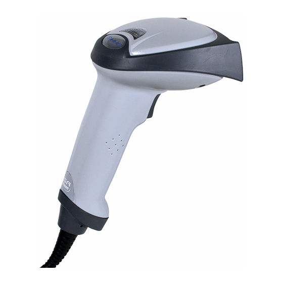
Getting Started The IMAGETEAM 5600 is a high performance retail and commercial linear imager from HHP. The IT5600 marks a new performance level for hand held scanners. Designed for today’s demanding retail and commercial environments, the IT5600 offers a superior reading range, durability, and the ability to read poor quality bar codes. -
Page 14: It5600 Models
IT5600 Models There are four models of the IT5600 scanner. In the designations listed below, “SR” indicates “Standard Range” linear optics. Refer to Chapter 6 programming information regarding Secondary Interfaces. Models Primary Secondary 5600SR000 TTL Level 232 Lower Power HHLC 5600SR010 Keyboard Wedge, TTL level Wand Emulation, TTL... -
Page 15: It5600 Scanner Identification
IT5600 Scanner Identification 1 - 3... -
Page 16: Connecting The Scanner When Powered By Host (Keyboard Wedge)
Connecting the Scanner When Powered by Host (Keyboard Wedge) A scanner can be connected between the keyboard and PC as a “keyboard wedge,” plugged into the serial port, or connected to a portable data terminal in wand emulation or non decoded output mode. The following is an example of a keyboard wedge connection: 1. -
Page 17: Reading Techniques
Reading Techniques The scanner has a view finder that projects a bright red aiming beam that corresponds to its horizontal field of view. The aiming line should be centered horizontally over the bar code; it will not read if the aiming line is in any other direction. -
Page 18: Keyboard Wedge
Note: After you scan one of the codes, power cycle the host terminal to have the interface in effect. Keyboard Wedge Note: This interface applies to the 5600SR010 and 5600SR050 models. The most common interface is Keyboard Wedge. The following Keyboard Wedge bar code also programs a carriage return (CR) suffix. -
Page 19: Wand Emulation Same Code
Wand Emulation Same Code Note: This interface applies to the 5600SR010 and 5600SR050 models. In Wand Emulation mode, the scanner decodes the bar code then sends data in the same format as a wand scanner. The Same Code format transmits U.P.C., EAN, Code 128 and Interleaved 2 of 5 bar codes without any changes, but converts all other symbologies to Code 39. -
Page 20: Ibm 4683 Ports 5B, 9B, And 17 Interface
IBM 4683 Ports 5B, 9B, and 17 Interface Note: This interface applies to the 5600SR010 and 5600SR050 models. Scan one of the following “Plug and Play” codes to program the 5600SR050 for IBM 4683 Port 5B, 9B, or 17. Note: After scanning one of these codes, you must power cycle the cash register. -
Page 21: Connecting The Scanner With Usb
Connecting the Scanner with USB Note: This interface applies to the 5600SR050 model only. A scanner can be connected to the USB port of a computer. 1. Connect the appropriate interface cable to the scanner and to the computer. 2. The scanner beeps. 3. -
Page 22: Connecting The Scanner With Serial Wedge
Each bar code above also programs the following suffixes for each symbology: Symbology Suffix EAN 8 EAN 13 UPC A UPC E Code 39 00 0A 0B Interleaved 2 of 5 00 0D 0B Code 128 00 18 0B Note: The following USB “Plug and Play” codes (USB Keyboard - PC, USB Keyboard - Mac, and USB HID) are supported on specific IT5600 models. - Page 23 Note: For the scanner to work properly, you must have the correct cable for your type of computer. To Host 4. Plug the serial connector into the serial port on your computer. Tighten the two screws to secure the connector to the port. 5.
- Page 24 1 - 12...
-
Page 25: Chapter 2 - Terminal Interfaces
Keyboard Wedge Connection Note: This interface applies to the 5600SR010 and 5600SR050 models. IMAGETEAM 5600 scanners are factory programmed for a keyboard wedge interface to an IBM PC AT with a USA keyboard. If this is your interface and you... -
Page 26: Supported Terminals
Supported Terminals Terminal Model(s) Terminal ID VT510, 520, 525 (PC style) VT510, 520, 525 (DEC style LK411) Esprit 200, 400 Heath Zenith PC, AT Vectra PS/2 25, 30, 77DX2 AT, PS/2 30–286, 50, 55SX, 60, 003 * 70, 70–061, 70–121, 80 IBM 102 key 3151, 3161, 3162, 3163, 3191, 3192, 3194, 3196, 3197, 3471,... -
Page 27: Keyboard Country
Country Code Scan Country Code Scan Belgium Italy Denmark Norway Finland Spain France Switzerland Germany/Austria USA (Default) Great Britain Save Note: Please refer to HHP’s website ( ) for complete keyboard www.HHP.com country support information and applicable interfaces. 2 - 3... -
Page 28: Keyboard Style
Keyboard Style This programs keyboard styles, such as Caps Lock and Shift Lock. Default = Regular. Regular is used when you normally have the Caps Lock key off. * Regular Caps Lock is used when you normally have the Caps Lock key on. Caps Lock Shift Lock is used when you normally have the Shift Lock key on (not common to U.S. -
Page 29: Keyboard Modifiers
Keyboard Modifiers This modifies special keyboard features, such as CTRL+ ASCII codes and Turbo Mode. Control + ASCII Mode On: The scanner sends key combinations for ASCII control characters for values 00-1F. Refer to Keyboard Function Relationships, page 8-1 for CTRL+ ASCII Values. Default = Off Control + ASCII Mode On * Control + ASCII Mode Off Turbo Mode: The scanner sends characters to a terminal faster. -
Page 30: Connecting The Scanner With Rs-232 Serial Port
Connecting the Scanner with RS-232 Serial Port Note: These instructions are for use with the RS-232 power stealer cable. 1. Turn off power to the terminal/computer. 2. Connect the appropriate interface cable to the scanner. Note: For the scanner to work properly, you must have the correct cable for your type of terminal/computer. -
Page 31: Rs-232 Baud Rate
RS-232 Baud Rate Baud Rate sends the data from the scanner to the terminal at the specified rate. The host terminal must be set for the same baud rate as the scanner. Default = 38,400 . 1200 2400 4800 9600 19200 * 38400 57,600... -
Page 32: Rs-232 Word Length: Data Bits, Stop Bits, And Parity
RS-232 Word Length: Data Bits, Stop Bits, and Parity Data Bits sets the word length at 7 or 8 bits of data per character. If an application requires only ASCII Hex characters 0 through 7F decimal (text, digits, and punctuation), select 7 data bits. For applications which require use of the full ASCII set, select 8 data bits per character. -
Page 33: Rs-232 Handshaking
RS-232 Handshaking RS-232 handshaking is a set of rules concerning the exchange of data between serially communicating devices. Default = RTS/CTS, XON/XOFF and ACK/ NAK Off RTS/CTS On * RTS/CTS Off XON/XOFF On * XON/OFF Off ACK/NAK On * ACK/NAK Off Wand Emulation Connection In Wand Emulation mode, the scanner decodes the bar code then sends data in the same format as a wand scanner. -
Page 34: Wand Emulation Transmission Rate
Wand Emulation Transmission Rate The Transmission Rate is limited by the terminal’s ability to receive data without dropping characters. Default = 25 inches/second. * 25 Wand Emulation Polarity The Polarity can be sent as standard with black bars high, or reversed with white bars high. -
Page 35: Wand Emulation Idle
Wand Emulation Idle The idle describes the state of the scanner when no data is being transmitted. When in Wand Emulation mode, you must set the scanner’s idle state to match the idle state for the device to which the scanner is connected. Default = Idle High . - Page 36 2 - 12...
-
Page 37: Chapter 3 - Output
Output Good Read Indicators Beeper – Good Read The beeper may be programmed On or Off in response to a good read. Turning this option off, only turns off the beeper response to a good read indication. All error and menu beeps are still audible. Default = On. * On Beeper Volume –... -
Page 38: Beeper Duration - Good Read
Beeper Duration – Good Read The beeper duration codes modify the length of the beep the scanner emits on a good read. Default = Normal. * Normal Beep Short Beep LED – Good Read The LED indicator can be programmed On or Off in response to a good read. Default = On. -
Page 39: Good Read Delay
Reread Delay only works when in automatic trigger mode (see page 3-5). * Short Medium Long Extra Long Good Read Delay This sets the minimum amount of time before the scanner can read another bar code. Default = No Delay. * No Delay Short Delay Medium Delay... - Page 40 When in serial mode, the scanner scans until a bar code has been read or until the deactivate command is sent. In serial mode, the scanner can also be set to turn itself off after a specified time has elapsed (see Serial Trigger Time Out, which follows).
-
Page 41: Automatic Trigger
Automatic Trigger The scanner scans continuously at full power with illumination fully on. Automatic Trigger Presentation Mode The LEDs are off until a bar code is presented to the scanner. Then the LEDs turn on automatically to read the code. Presentation Mode uses ambient light to detect the bar codes. - Page 42 To change the width of the window to a value other than 20%, scan the Centering On bar code below and scan a value (percentage from 1 to 100) and SAVE from the Programming Chart inside the back cover of this manual. Centering On The figure below illustrates the percentage range from 1 to 100%.
-
Page 43: Chapter 4 - Data Editing
Data Editing Prefix/Suffix Overview When a bar code is scanned, additional information is sent to the host computer along with the bar code data. This group of bar code data and additional, user-defined data is called a “message string.” The selections in this section are used to build the user-defined data into the message string. -
Page 44: Symbology Chart
To Add a Prefix or Suffix: Step 1. Scan the Add Prefix or Add Suffix symbol (page 4-4). Step 2. Determine the 2 digit Hex value from the Symbology Chart (included in Appendix A) for the symbology to which you want to apply the prefix or suffix. -
Page 45: To Clear One Or All Prefixes Or Suffixes
To Clear One or All Prefixes or Suffixes: You can clear a single prefix or suffix, or clear all prefixes/suffixes for a symbology. When you Clear One Prefix (Suffix), the specific character you select is deleted from the symbology you want. When you Clear All Prefixes (Suffixes), all the prefixes or suffixes for a symbology are deleted. -
Page 46: Prefix Selections
Prefix Selections Add Prefix Clear One Prefix Clear All Prefixes Suffix Selections Add Suffix Clear One Suffix Clear All Suffixes Function Code Transmit When this selection is enabled and function codes are contained within the scanned data, the scanner transmits the function code to the terminal. Charts of these function codes are provided in Supported Interface Keys starting on... -
Page 47: Intercharacter Delay
Intercharacter Delay An intercharacter delay of up to 495 milliseconds may be placed between the transmission of each character of scanned data. Scan the Intercharacter Delay bar code below, then scan the number of milliseconds and the SAVE bar code using the Programming Chart inside the back cover of this manual. -
Page 48: Interfunction Delay
Interfunction Delay An interfunction delay of up to 495 milliseconds may be placed between the transmission of each segment of the message string. Scan the Interfunction Delay bar code below, then scan the number of milliseconds and the SAVE bar code using the Programming Chart inside the back cover of this manual. -
Page 49: Chapter 5 - Data Formatting
Data Formatting Data Format Editor Introduction You may use the Data Format Editor to change the scanner’s output. For example, you can use the Data Format Editor to insert characters at certain points in bar code data as it is scanned. The selections in the following pages are used only if you wish to alter the output. -
Page 50: Other Programming Selections
Note: The wildcard for all terminal types is 099. Step 4. Code I.D. In the Appendix A, find the symbology to which you want to apply the data format. Locate the Hex value for that symbology and scan the 2 digit hex value from the Programming Chart inside the back cover of... - Page 51 hex values for ASCII codes, see ASCII Conversion Chart (Code Page 1252) on page A-2.) F4 Send “xx” character “nn” times (Insert) leaving cursor in current cursor posi- tion. Syntax = F4xxnn (xx stands for the hex value for an ASCII code, see ASCII Conversion Chart (Code Page 1252) on page A-2, and nn is the numeric value (00-99) for the number of times it should be sent.)
-
Page 52: Data Format Editor
tax = E4nnxx ...zz where nn is the total count of both characters to be replaced plus replacement characters; xx defines charac- ters to be replaced and xx defines replacement characters, continuing through zz and zz E5 Terminates character replacement. Syntax = E5. FE Compare character in current cursor position to the character “xx.”... -
Page 53: Data Formatter
Data Formatter When Data Formatter is turned off, the bar code data is output to the host as read (including prefixes and suffixes). Choose one of the following options. Default = Data Formatter On. * Data Formatter On, but Not Required Data Formatter Off When Data Formatter is required, all input data must conform to an edited format or the scanner does not transmit the input data to the host device. - Page 54 5 - 6...
-
Page 55: Chapter 6 - Secondary Interface
Secondary Interface By switching secondary interface cables, the IT5600 scanner, for example, can communicate with a portable data terminal (secondary interface) in addition to the host terminal (primary interface). See the table below for the secondary interfaces for each IT5600 model. Models Primary Secondary... -
Page 56: Secondary Non Decoded Output Laser Emulation
RS-232 programmable selections are used by both the primary and secondary interfaces. Changing an RS-232 parameter (e.g., baud rate or parity), while in primary or secondary mode will affect both interfaces. If you want to change the RS-232 settings, refer to the Connecting the Scanner with RS-232 Serial Port section on pages 2-6 to 2-9. -
Page 57: Non Decoded Laser Emulation Idle
Non Decoded Laser Emulation Idle The idle describes the state of the scanner when no data is being transmitted. When in Non Decoded mode, you must set the scanner’s idle state to match the idle state for the device to which the scanner is connected. Default = Idle High. Idle Low * Idle High Disabling the Secondary Interface... - Page 58 Presentation Mode: The LEDs are off until a bar code is presented to the scanner. Then the LEDs turn on automatically to read the code. Presentation Mode uses ambient light to detect the bar codes. Presentation Mode Manual Trigger, Low Power: Scan the Manual Trigger, Low Power bar code below and the scanner “sleeps”...
-
Page 59: Introduction
Symbologies Introduction This programming section contains the following menu selections. Refer to Chapter 10 for settings and defaults. • All Symbologies • IATA Code 2 of 5 • China Post • Interleaved 2 of 5 • Codabar • Korea Post •... -
Page 60: Message Length
Message Length You are able to set the valid reading length of some of the bar code symbologies. If the data length of the scanned bar code doesn’t match the valid reading length, the scanner will issue an error beep. You may wish to set the same value for minimum and maximum length to force the scanner to read fixed length bar code data. -
Page 61: Codabar
Codabar <Default All Codabar Settings> Codabar * On Codabar Start/Stop Characters Start/Stop characters identify the leading and trailing ends of the bar code. You may either transmit, or not transmit Start/Stop characters. Default = Don’t Transmit . Transmit * Don’t Transmit Codabar Check Character Codabar check characters are created using different “modulos.”... -
Page 62: Codabar Concatenation
When Check Character is set to Validate, but Don’t Transmit , the unit will only read Codabar bar codes printed with a check character, but will not transmit the check character with the scanned data. * No Check Character Validate Modulo 16, but Don’t Transmit Validate Modulo 16 and Transmit Codabar Concatenation... -
Page 63: Codabar Message Length
Codabar Message Length Scan the bar codes below to change the message length. Refer to Message Length on page 7-2 for additional information. Minimum and Maximum lengths = 2-60. Minimum Default = 4, Maximum Default = 60. Minimum Message Length Maximum Message Length Code 39 <... -
Page 64: Code 39 Check Character
Code 39, continued Code 39 Check Character No Check Character indicates that the scanner reads and transmits bar code data with or without a check character. When Check Character is set to Validate, but Don’t Transmit, the unit only reads Code 39 bar codes printed with a check character, but will not transmit the check character with the scanned data. -
Page 65: Code 39 Append
Code 39, continued Code 39 Append This function allows the scanner to append the data from several Code 39 bar codes together before transmitting them to the host computer. When this function is enabled, the scanner stores those Code 39 bar codes that start with a space (excluding the start and stop symbols), and does not immediately transmit the data. -
Page 66: Full Ascii
Full ASCII If Full ASCII Code 39 decoding is enabled, certain character pairs within the bar code symbol will be interpreted as a single character. For example: $V will be decoded as the ASCII character SYN, and /C will be decoded as the ASCII character #. -
Page 67: Check Digit
Interleaved 2 of 5 < Default All Interleaved 2 of 5 Settings > Interleaved 2 of 5 * On Check Digit No Check Digit indicates that the scanner reads and transmits bar code data with or without a check digit. When Check Digit is set to Validate, but Don’t Transmit, the unit only reads Interleaved 2 of 5 bar codes printed with a check digit, but will not transmit the check digit with the scanned data. -
Page 68: Interleaved 2 Of 5 Message Length
Interleaved 2 of 5 Message Length Scan the bar codes below to change the message length. Refer to Message Length on page 7-2 for additional information. Minimum and Maximum lengths = 2-80. Minimum Default = 4, Maximum Default = 80. Minimum Message Length Maximum Message Length Code 93... -
Page 69: Code 2 Of 5
Code 2 of 5 <Default All Code 2 of 5 Settings> Code 2 of 5 * Off Code 2 of 5 Message Length Scan the bar codes below to change the message length. Refer to Message Length on page 7-2 for additional information. Minimum and Maximum lengths = 1-48. -
Page 70: Iata Code 2 Of 5 Message Length
IATA Code 2 of 5, continued * Off IATA Code 2 of 5 Message Length Scan the bar codes below to change the message length. Refer to Message Length on page 7-2 for additional information. Minimum and Maximum lengths = 1-48. Minimum Default = 4, Maximum Default = 48. Minimum Message Length Maximum Message Length Matrix 2 of 5... -
Page 71: Matrix 2 Of 5 Message Length
Matrix 2 of 5 Message Length Scan the bar codes below to change the message length. Refer to Message Length on page 7-2 for additional information. Minimum and Maximum lengths = 1-80. Minimum Default = 4, Maximum Default = 80. Minimum Message Length Maximum Message Length Code 11... -
Page 72: Code 11 Message Length
Code 11, continued Code 11 Message Length Scan the bar codes below to change the message length. Refer to Message Length on page 7-2 for additional information. Minimum and Maximum lengths = 1-80. Minimum Default = 4, Maximum Default = 80. Minimum Message Length Maximum Message Length Code 128... -
Page 73: Isbt 128 Concatenation
Code 128, continued ISBT 128 Concatenation In 1994 the International Society of Blood Transfusion (ISBT) ratified a standard for communicating critical blood information in a uniform manner. The use of ISBT formats requires a paid license. The ISBT 128 Application Specification describes 1) the critical data elements for labeling blood products, 2) the current recommendation to use Code 128 due to its high degree of security and its space-efficient design, 3) a variation of Code 128 that supports concatenation of... -
Page 74: Telepen
Telepen, continued Telepen * Off Telepen Output Using AIM Telepen Output, the scanner reads symbols with start/stop pattern 1 and decodes them as standard full ASCII (start/stop pattern 1). When Original Telepen Output is selected, the scanner reads symbols with start/stop pattern 1 and decodes them as compressed numeric with optional full ASCII (start/stop pattern 2). -
Page 75: Upc A
UPC A <Default All UPC A Settings> UPC A * On UPC A Check Digit This selection allows you to specify whether the check digit should be transmitted at the end of the scanned data or not. Default = On. * On UPC A Number System The numeric system digit of a U.P.C. -
Page 76: Upc A Addenda
UPC A, continued UPC A Addenda This selection adds 2 or 5 digits to the end of all scanned UPC A data. Default = Off for both 2 Digit and 5 Digit Addenda. 2 Digit Addenda On * 2 Digit Addenda Off 5 Digit Addenda On * 5 Digit Addenda Off UPC A Addenda Required... -
Page 77: Upc-A/Ean-13 With Extended Coupon Code
UPC-A/EAN-13 with Extended Coupon Code Use the following codes to enable or disable UPC-A and EAN-13 with Extended Coupon Code. Default = On. * On UPC E <Default All UPC E Settings> UPC E0 and UPC E1 Most U.P.C. bar codes lead with the 0 number system. For these codes, use the UPC E0 selection. -
Page 78: Upc E0 And Upc E1 Expand
UPC E, continued UPC E0 and UPC E1 Expand UPC E Expand expands the UPC E code to the 12 digit, UPC A format. Default = Off. * Off UPC E0 and UPC E1 Addenda Required When Addenda Required is set to on, the scanner will only read UPC E bar codes that have addenda. -
Page 79: Upc E0 Check Digit
UPC E, continued UPC E0 Check Digit Check Digit specifies whether the check digit should be transmitted at the end of the scanned data or not. Default = On. * On UPC E0 Number System The numeric system digit of a U.P.C. symbol is normally transmitted at the beginning of the scanned data, but the unit can be programmed so it will not transmit it. -
Page 80: Ean/Jan 13 Check Digit
EAN/JAN 13 <Default All EAN/JAN Settings> EAN/JAN 13 * On EAN/JAN 13 Check Digit This selection allows you to specify whether the check digit should be transmitted at the end of the scanned data or not. Default = On. * On EAN/JAN 13 Addenda This selection adds 2 or 5 digits to the end of all scanned EAN/JAN 13 data. -
Page 81: Ean/Jan 13 Addenda Required
EAN/JAN 13, continued EAN/JAN 13 Addenda Required When Addenda Required is set to on, the scanner will only read EAN/JAN 13 bar codes that have addenda. Default = Not Required. Required * Not Required EAN/JAN 13 Addenda Separator When this feature is on, there is a space between the data from the bar code and the data from the addenda. -
Page 82: Ean/Jan 8
EAN/JAN 8 <Default All EAN/JAN 8 Settings> EAN/JAN 8 * On EAN/JAN 8 Check Digit This selection allows you to specify whether the check digit should be transmitted at the end of the scanned data or not. Default = On. * On EAN/JAN 8 Addenda This selection adds 2 or 5 digits to the end of all scanned EAN/JAN 8 data. -
Page 83: Ean/Jan 8 Addenda Required
EAN/JAN 8, continued EAN/JAN 8 Addenda Required When Addenda Required is set to on, the scanner will only read EAN/JAN 8 bar codes that have addenda. Default = Not Required. Required * Not Required EAN/JAN 8 Addenda Separator When this feature is on, there is a space between the data from the bar code and the data from the addenda. -
Page 84: Msi Check Character
MSI, continued MSI Check Character Different types of check characters are used with MSI bar codes. You can program the scanner to read MSI bar codes with Type 10 check characters. Default = Validate Type 10, but Don’t Transmit. When Check Character is set to Validate and Transmit , the scanner will only read MSI bar codes printed with the specified type check character, and will transmit this character at the end of the scanned data. -
Page 85: Plessey Code
Plessey Code <Default All Plessey Code Settings> Plessey Code * Off Plessey Message Length Scan the bar codes below to change the message length. Refer to Message Length on page 7-2 for additional information. Minimum and Maximum lengths = 4-48. Minimum Default = 4, Maximum Default = 48. Minimum Message Length Maximum Message Length RSS-14... -
Page 86: Rss Limited
RSS-14, continued RSS-14 * On RSS Limited < Default All RSS Limited Settings > RSS Limited * On RSS Expanded < Default All RSS Expanded Settings > 7 - 28... -
Page 87: Rss Expanded
RSS Expanded, continued RSS Expanded * On RSS Expanded Message Length Scan the bar codes below to change the message length. Refer to Message Length on page 7-2 for additional information. Minimum and Maximum lengths = 4-74. Minimum Default = 4, Maximum Default = 74. Minimum Message Length Maximum Message Length China Post Code... -
Page 88: Korea Post Code
China Post Code, continued China Post Message Length Scan the bar codes below to change the message length. Refer to Message Length on page 7-2 for additional information. Minimum and Maximum lengths = 2-80. Minimum Default = 4, Maximum Default = 80. Minimum Message Length Maximum Message Length Korea Post Code... -
Page 89: Korea Post Message Length
Korea Post, continued Korea Post Message Length Scan the bar codes below to change the message length. Refer to Message Length on page 7-2 for additional information. Minimum and Maximum lengths = 2-80. Minimum Default = 4, Maximum Default = 48. Minimum Message Length Maximum Message Length PosiCode... -
Page 90: Posicode Message Length
PosiCode, continued You have to have PosiCode A and B on to read any of the PosiCode symbologies. A and B On (No Limited) A and B and Limited A On (Limited B Off) * A and B and Limited B On (Limited A Off) PosiCode Message Length Scan the bar codes below to change the message length. -
Page 91: Codablock F
Codablock F <Default All Codablock F Settings> Codablock F * Off Codablock F Message Length Scan the bar codes below to change the message length. Refer to Message Length on page 7-2 for additional information. Minimum and Maximum lengths = 1-2048. Minimum Default = 1, Maximum Default = 2048. Minimum Message Length Maximum Message Length Code 16K... -
Page 92: Code 16K
Code 16K * Off Code 16K Message Length Scan the bar codes below to change the message length. Refer to Message Length on page 7-2 for additional information. Minimum and Maximum lengths = 0-160. Minimum Default = 1, Maximum Default = 160. Minimum Message Length Maximum Message Length Code 49... -
Page 93: Code 49 Message Length
Code 49 Message Length Scan the bar codes below to change the message length. Refer to Message Length on page 7-2 for additional information. Minimum and Maximum lengths = 1-81. Minimum Default = 1, Maximum Default = 81. Minimum Message Length Maximum Message Length 7 - 35... - Page 94 7 - 36...
-
Page 95: Chapter 8 - Interface Keys
Interface Keys Keyboard Function Relationships The following Keyboard Function Code, Hex/ASCII Value, and Full ASCII “CTRL”+ relationships apply to all terminals that can be used with the scanner. Refer to page 2-5 enable Control + ASCII mode. Function Code HEX/ASCII Value Full ASCII “CTRL”... - Page 96 The last five characters in the Full ASCII “CTRL”+ column ( [ \ ] 6 - ), apply to US only. The following chart indicates the equivalents of these five characters for different countries. Codes Country United States Belgium < Scandinavia <...
-
Page 97: Supported Interface Keys
Supported Interface Keys IBM AT/XT and PS/2 Compatibles, IBM XTs and IBM, DDC, Memorex WYSE PC/AT Compatibles Telex, Harris* ASCII Supported Keys Supported Keys Supported Keys Reserved Reserved Reserved Enter (KP) CR/Enter Enter Cap Lock Caps Lock ALT make Reserved ALT break Reserved CTRL make... - Page 98 Supported Interface Keys IBM, Memorex Telex (102)* Memorex Telex (88)** ASCII Supported Keys Supported Keys Reserved Reserved Enter Enter PF10 PF11 PF12 Reserved Reserved New Line New Line Field Forward Field Forward Reserved Tab/Field Forward Field Forward Delete Delete Field Exit New Line Insert Insert...
- Page 99 Supported Interface Keys Esprit 200, 400 Esprit 200, 400 Esprit 200, 400 ANSI ASCII ASCII Supported Keys Supported Keys Supported Keys Reserved Reserved Reserved New Line New Line New Line New Line New Line New Line Delete New Line New Line New Line Insert Escape...
- Page 100 Supported Interface Keys Apple Mac/iMac ASCII Supported Keys Reserved Enter/Numpad Enter CAPS ALT make ALT break CNTRL make CNTRL break RETURN APPLE make APPLE break RETURN Ins Help Home Prnt Scrn BACKSPACE LSHIFT TAB BACKSPACE 8 - 6...
-
Page 101: Chapter 9 - Utilities
Utilities To Add a Test Code I.D. Prefix to All Symbologies This selection allows you to turn on transmission of a Code I.D. before the decoded symbology. (See the Symbology Chart, included in the Appendix A, page A-1) for the single character code that identifies each symbology.) This action first clears all current prefixes, then programs a Code I.D. -
Page 102: Temporary Visual Menu Configuration
Temporary Visual Menu Configuration For quick download communication configuration, scan the Visual Menu bar code to temporarily configure the scanner for Visual Menu settings. Note: If you have a unit capable of keyboard wedge mode, scan the bar code below and the unit will communicate in RS-232 mode, allowing it to work with Visual Menu. -
Page 103: Chapter 10 - Serial Programming Commands
Serial Programming Commands The serial programming commands can be used in place of the programming bar codes. Both the serial commands and the programming bar codes will program the IT5600. For complete descriptions and examples of each serial programming command, refer to the corresponding programming bar code in this manual. -
Page 104: Query Commands
Query Commands Several special characters can be used to query the device about its settings. What is the default value for the setting(s). What is the device’s current value for the setting(s). What is the range of possible values for the setting(s). (The de- vice’s response uses a dash (-) to indicate a continuous range of values. -
Page 105: Examples Of Query Commands
When responding, the device echoes back the command sequence with the status character inserted directly before each of the punctuation marks (the period, exclamation point, comma, or semicolon) in the command. Examples of Query Commands In the following examples, a bracketed notation [ ] depicts a non-displayable response. -
Page 106: Trigger Commands
Trigger Commands You can activate and deactivate the scanner with serial trigger commands. First, the scanner must be put in Manual/Serial Trigger Mode either by scanning the Manual/Serial Trigger Mode bar code (page 3-3), or by sending the Manual/ Serial Menu Command (page 10-7). Once the scanner is in serial trigger mode, the trigger is activated and deactivated by sending the following commands: Activate:SYN T CR Deactivate:SYN U CR... -
Page 107: Menu Commands
Menu Commands Serial Setting Command Selection Page * Indicates default # Indicates a numeric entry Factory Default Settings Default DEFALT Terminal Interfaces 003 (5600SR010/050 models) Terminal ID TERMID### 000 (5600SR000/030 models) *USA KBDCTY0 Program Keyboard Country Other countries KBDCTY## Keyboard Style *Regular KBDSTY0 Caps Lock... -
Page 108: Output Selections
Serial Setting Command Selection Page * Indicates default # Indicates a numeric entry 7 Data, 1 Stop, Parity Even 232WRD3 7 Data, 1 Stop, Parity None 232WRD0 7 Data, 1 Stop, Parity Odd 232WRD6 7 Data, 2 Stop, Parity Even 232WRD4 Word Length: Data Bits, 7 Data, 2 Stop, Parity None... - Page 109 Serial Setting Command Selection Page * Indicates default # Indicates a numeric entry BEPLVL0 *Low BEPLVL1 Beeper Volume - Good Read Medium BEPLVL2 High BEPLVL3 Low (1600) (min 400Hz) BEPFQ11600 Beeper Pitch - Good Read *Medium (3250) BEPFQ13250 (Frequency) High (4200) (max 9000Hz) BEPFQ14200 *Normal Beep BEPBIP0...
-
Page 110: Data Formatter Selections
Serial Setting Command Selection Page * Indicates default # Indicates a numeric entry Add Prefix PREBK2## Prefix Clear One Prefix PRECL2 Clear All Prefixes PRECA2 Add Suffix SUFBK2## Suffix Clear One Suffix SUFCL2 Clear All Suffixes SUFCA2 *Enable RMVFNC0 Function Code Transmit Disable RMVFNC1 Intercharacter Delay... - Page 111 Serial Setting Command Selection Page * Indicates default # Indicates a numeric entry Black High HLCPOL0 Non Decoded Output Laser Emulation Polarity *White High HLCPOL1 HLCIDL0 Non Decoded Output Laser Emulation Idle *High HLCIDL1 *Disable 2IF_EN0 Disabling the Secondary Interface Enable 2IF_EN1 *Manual Trigger...
- Page 112 Serial Setting Command Selection Page * Indicates default # Indicates a numeric entry *No Check Char. C39CK20 Validate, But Don’t C39CK21 Code 39 Check Char. Transmit Validate, C39CK22 and Transmit Minimum (0 - 48) *0 C39MIN## Code 39 Message Length Maximum (0 - 48) *48 C39MAX## *Off...
- Page 113 Serial Setting Command Selection Page * Indicates default # Indicates a numeric entry Default All IATA Code 2 of 5 IATA Code 2 of 5 A25DFT 7-12 Settings *Off A25ENA0 7-12 IATA Code 2 of 5 A25ENA1 7-12 Minimum (1 - 48) *4 A25MIN## 7-12 IATA Code 2 of 5 Message...
- Page 114 Serial Setting Command Selection Page * Indicates default # Indicates a numeric entry Minimum (1 - 60) *1 TELMIN## 7-16 Telepen Message Length Maximum (1 - 60) *60 TELMAX## 7-16 Default All UPC A UPADFT 7-17 UPC A Settings UPAENA0 7-17 UPC A UPAENA1...
- Page 115 Serial Setting Command Selection Page * Indicates default # Indicates a numeric entry *Not Required UPEARQ0 7-20 UPC E Addenda Required Required UPEARQ1 7-20 UPEADS0 7-20 UPC E Addenda Separator UPEADS1 7-20 Default All EAN/ EAN/JAN 13 E13DFT 7-22 JAN 13 Settings E13ENA0 7-22 EAN/JAN 13...
- Page 116 Serial Setting Command Selection Page * Indicates default # Indicates a numeric entry CPNENA0 7-25 Coupon Code CPNENA1 7-19 Default All MSI Settings MSIDFT 7-25 *Off MSIENA0 7-25 MSIENA1 7-25 *Validate Type 10, but Don’t MSICHK0 7-26 Transmit MSI Check Character Validate Type 10 and MSICHK1 7-26...
- Page 117 Serial Setting Command Selection Page * Indicates default # Indicates a numeric entry Minimum (2 - 80) *4 CPCMIN## 7-30 China Post Code Msg. Length Maximum (2 - 80) *80 CPCMAX## 7-30 Default All Korea Post Code Korea Post Code KPCDFT 7-30 Settings...
- Page 118 10 - 16...
-
Page 119: Chapter 11 - Product Specifications
Product Specifications IMAGETEAM 5600 Product Specifications Parameter Specification Dimensions (Typical): Height 6.2 inches (15.7 cm) Length 5.3 inches (13.5 cm) Width 3.2 inches (8.1 cm) Weight 6.5 ounces (185 g) Light Source 630 nm visible red LED Scan Rate 270 scans per second in most usages ±65 degrees... -
Page 120: Depth Of Field
Depth of Field Minimum Bar Maximum Near Minimum Far Field Width Field (no ambient lighting) 13 mil 100% UPC 1 in (2.5 cm) 24 in (61 cm) 7.5 mil Code 39 4 in (10 cm) 14 in (36 cm) 10 mil Code 39 2 in (5 cm) 18 in (46 cm) 13 mil Code 39... -
Page 121: Standard Cable Pinouts
Standard Cable Pinouts Laser Output Only (Laser Compatible Bar Image) 11 - 3... - Page 122 Standard Cable Pinouts Keyboard Wedge 11 - 4...
- Page 123 Standard Cable Pinouts Wand Emulation 11 - 5...
- Page 124 Standard Cable Pinouts (Primary Interface Cables) Serial Output 11 - 6...
- Page 125 Standard Cable Pinouts 11 - 7...
- Page 126 11 - 8...
-
Page 127: Chapter 12 - Maintenance
Inspect the scanner’s interface cable and connector for wear or other signs of damage. A badly worn cable or damaged connector may interfere with scanner operation. Contact your HHP distributor for information about cable replacement. Cable replacement instructions are on page 12-2. -
Page 128: Replacing The Interface Cable
The interface cable is designed to be field replaceable. • Order replacement cables from HHP or from an authorized distributor. • When ordering a replacement cable, specify the cable part number of the original interface cable. - Page 129 Is the scanner having trouble reading your symbols? If the scanner isn’t reading symbols well, check that the symbols: • Aren’t smeared, rough, scratched, or exhibiting voids. • Aren’t coated with frost or water droplets on the surface. • Are enabled in the scanner or in the decoder to which the scanner connects. Is the bar code displayed but not entered? The bar code is displayed on the host device correctly, but you still have to press a key to enter it (the Enter/Return key or the Tab key, for example).
- Page 130 12 - 4...
-
Page 131: Chapter 13 - Customer Support
Kingdom. To obtain warranty or non-warranty service, return the unit to HHP (postage paid) with a copy of the dated purchase record attached. In the United States, please contact the HHP Product Service Department at the address/telephone number listed below to obtain a Return Material Authorization number (RMA #) before returning the product. -
Page 132: Help Desk
Unit 04, 11/F., Emperor Group Centre No. 288 Hennessy Road Wanchai, Hong Kong Telephone: +852-2511-3050 Fax: +852-251-13557 For service in Japan, please contact your HHP representative (at the address that follows) or your local distributor. Japan Office Hand Held Products, Inc. 1-4-1 Koishikawa... - Page 133 Asia: Telephone:+852-2511-3050 E-mail: asia_support@hhp.com Latin America: Telephone:(239) 263-7600 E-mail: la_support@hhp.com 13 - 3...
-
Page 134: Limited Warranty
HHP without a Return Materials Authorization, which may be obtained by contacting HHP. In the event that the product is returned to HHP or its authorized service center within the Warranty Period and HHP determines to... - Page 135 Appendix A Symbology Chart Code Code Symbology Symbology China Post IATA 2 of 5 Codabar Interleaved 2 of 5 Codablock F Korea Post Code 2 of 5 Matrix 2 of 5 Code 11 Code 16K ]K m Plessey Code Code 39 PosiCode <...
- Page 136 ASCII Conversion Chart (Code Page 1252 Char Char Char Char ‘ “ & ‘ < > A - 2...
- Page 137 Dec. Char Dec. Char Dec. Char Dec. Char € À à ¡ Á á ‚ ¢ Â â ƒ £ Ã ã „ ¤ Ä ä … ¥ Å å † ¦ Æ æ ‡ § Ç ç ˆ ¨ È...
- Page 138 A - 4...
-
Page 140: Sample Symbols
Sample Symbols UPC A 0 123456 7890 Interleaved 2 of 5 1234567890 Code 128 Code 128 EAN 13 9 780330 290951 EAN 8 3210 5 UPC-E 456123... - Page 141 Sample Symbols Code 39 Codabar BC321 Code 93 A13579B Code 2 of 5 123456-9$ Matrix 2 of 5 123456 6543210 RSS-14 (01)00123456789012...
-
Page 143: Programming Chart
Programming Chart Discard Save Note: If you make an error while scanning the letters or digits (before scanning Save), scan Discard, scan the correct letters or digits, and Save again. - Page 144 5600/UG Rev B...
Need help?
Do you have a question about the IMAGETEAM 5600 and is the answer not in the manual?
Questions and answers