Table of Contents
Advertisement
Quick Links
Advertisement
Table of Contents
Troubleshooting

Related Manuals for KAR-TECH CAN RANGER

Summary of Contents for KAR-TECH CAN RANGER
- Page 1 CAN RANGER RADIO/CAN REMOTE CONTROL SYSTEM OPERATION MANUAL...
-
Page 2: Table Of Contents
CAN RANGER OPERATION 3B1901EJ | REV. DATE: July 23, 2019 TABLE OF CONTENTS DESCRIPTION ................... 2 SYSTEM OPERATION ................. 3 TRANSMITTER AND RECEIVER SYNCHRONIZATION ......5 OUTPUTS ..................8 BATTERY CHARGING ................. 9 INSTALLATION ................10 BEFORE APPLYING POWER! ............10 CAN ACTUATOR ID ASSIGNMENT ............ -
Page 3: Description
CAN RANGER OPERATION associated optional equipment DESCRIPTION such as Palm™ interface tools. The CAN RANGER is a state of the art microprocessor based The transmitter is equipped Radio Frequency (RF) control with joysticks toggle system. It will provide the switches for various functions. -
Page 4: System Operation
CAN RANGER OPERATION The receiver has an RS-232 the CAN Ranger, and the CAN communication port Actuators. interface with optional Palm Pilot diagnostic tool. To turn on the transmitter, turn the key switch to the ON RANGER system position. To turn it off, turn... - Page 5 NC contact on fails or someone moves a the relay to stop the engine. handle) the CAN Ranger will stop the engine. This is a The normal configuration for safety feature to protect the...
-
Page 6: Transmitter And Receiver Synchronization
CAN RANGER OPERATION continue center 1. Receiver valve/handle. transmitter power should be off TRANSMITTER AND 2. Press E-STOP switch, RECEIVER SYNCHRONIZATION position BOOM toggle switch NORMAL, Each radio transmitter WINCH switch to FAST, preprogrammed with a unique and BASKET LEVELING radio ID code. - Page 7 CAN RANGER OPERATION If the ATB Input is enabled LEDs on transmitter will in calibration and the ATB stop toggling and the input is driven high (12/24V), green will blink the red and green LEDs on rapidly to indicate that...
- Page 8 CAN RANGER OPERATION (or zero) the angle sensor, system. The 5 push buttons position the bucket to what on the controller are used to you want level to be. NOTE: navigate through the screens. This must be within 5 degrees of what the sensor thinks is 0.
-
Page 9: Outputs
CAN RANGER OPERATION The LCD CONTRAST Menu outputs can also detect a no- lets adjust load or broken wire condition. Contrast. These error conditions evident LOCAL OPERATION Menu lets indicator or the alphanumeric Receiver’s buttons display receiver manually control module or the HISTOGRAM actuators. -
Page 10: Battery Charging
CAN RANGER OPERATION NOT activated, and will detect none switches short activated. joysticks (if equipped) is used proportional outputs will for period of 10 minutes. The detect no-load short user must recycle power to condition WHEN activated. restore transmitter operation. -
Page 11: Installation
CAN RANGER OPERATION • Verify that the transmitter INSTALLATION battery is fully charged. If Refer KAR-TECH it is low, performance may INSTALLATION manual be erratic. guidance on all aspects of • Read rest this installation specific to your manual. truck. Additionally, refer to... -
Page 12: Can Actuator Id Assignment
CAN RANGER OPERATION CAN ACTUATOR ID ASSIGNMENT Using the buttons on the CAN Ranger Receiver, navigate Kar-Tech CAN Actuators are through the LCD screens to pre-assigned at the factory CALIBRATION. Press <SET>. and labeled for each function. arrow buttons following... - Page 13 CAN RANGER OPERATION • the actuators are connected If you skip an actuator to the system. Each time the during assignment operator tells receiver process, the Receiver will which actuator was added, not know, and will not the receiver will assign that assign that actuator.
-
Page 14: Actuator Calibration
CAN RANGER OPERATION actuator’s ZERO enter password 1262. position Enter password correct. pressing <SET>. Then press strange/incorrect position the right button (FWD arrow) readings, this may be the to get to: reason. ACTUATOR SETUP PUSH SET Next presses the right button... - Page 15 CAN RANGER OPERATION neutral position (Valve handle. center). ENGINE STOP POSITION FAST POSITION This is the position of the This position valve handle right before actuator moves to when the hydraulics flow function transmitter’s BOOM SPEED movement. receiver switch is switched to NORMAL...
- Page 16 CAN RANGER OPERATION enabled if the valve spring is weak. In each setting screen both stored value SWING CALIBRATION current actuator position are shown on the second row of this first time the display. calibrating the actuators, start with SWING SETUP and the ←...
- Page 17 CAN RANGER OPERATION actuator Handle all the way in the functioning correctly. Try the direction Counter other handles to see if the Clockwise Swing. Hold it there other handles and push <SET>. control the displayed position. swap actuator Next Slow...
- Page 18 CAN RANGER OPERATION PUSH SET TO SAVE Next Slow Clockwise USE ↑ TO QUIT Swing needs to be set. Hold Pushing <SET> will save the the SWING Handle in the settings. Pushing ↑ will exit position for slow Clockwise the Swing Calibration and will Swing, and push <SET>.
-
Page 19: Actuator Calibration Using The Transmitter
CAN RANGER OPERATION crane works properly with remote before delivery. ACTUATOR CALIBRATION USING THE TRANSMITTER This procedure is similar to calibration using valve handles, instead you will be using the joysticks to move the actuator to the desired position and pressing Horn... -
Page 20: Rpm Calibration
Use ↑ RPM CALIBRATION to increase the selected digit PLEASE NOTE: THE KAR- or ↓ to decrease it. Use ← to TECH CAN RANGER CAN BE back out of this screen and CONFIGURED TO PROVIDE return Calibration... - Page 21 CAN RANGER OPERATION Bump Throttle Bump Throttle sends a pulse Cruise Control to ECM through RPM+ output On Off Throttle (PIN connector ‘CA’) which increments the engine Inverted PWM RPM to the next sequential Analog setting. These are set in the...
- Page 22 CAN RANGER OPERATION PWM generates a pulse width generates Analog modulated output with voltage that varies to change amplitude of BATTERY + on engine’s PWM/Analog output (Pin1 of PWM/Analog output (Pin1 of CA). The percentage of time CA). parameters that...
- Page 23 CAN RANGER OPERATION switch SLOW position. step size larger when the SPEED switch is in the FAST position. If not using transmitter calibrate the RPM Actuator, just physically move actuator into the Idle and Max positions when instructed. After going...
-
Page 24: Option Setup
CAN RANGER OPERATION this ENABLE (ENB). OPTION SETUP Otherwise disable it (DIS). If Using the buttons on the CAN you leave it enabled but do Ranger Receiver, navigate not have the feature, you will through the LCD screens to errors... - Page 25 CAN RANGER OPERATION Tilt feature, you can set 3 Debounce is used to smooth parameters, TILT WINDOW, angle sensor’s TILT DELAY, TILT readings. your machine DEBOUNCE. vibrates a lot, use a higher Tilt Debounce. your Tilt Window is in degrees. It is...
- Page 26 CAN RANGER OPERATION goes high (active). The output when it goes high (active), will ramp off to allow for a transmitter’s LEDs will smooth stop. If you do not flash together when a joystick want either of these features, is operated. In CCW STOP just disable Input 1.
- Page 27 CAN RANGER OPERATION Next Auxiliary setup Next the TELE 2 setup screen screen will appear: will appear: DISABLE TELE 2 DIS THEN PUSH SET THEN PUSH SET Use ↑ or ↓ to select between Use ↑ or ↓ to toggle between...
- Page 28 CAN RANGER OPERATION Next BOOM setup Next the Units setup screen screen will appear: will appear: BOOM 2 DIS UNIT ENGLISH THEN PUSH SET THEN PUSH SET Use ↑ or ↓ to toggle between Use ↑ or ↓ to toggle between...
- Page 29 CAN RANGER OPERATION TIME, the CAN Actuator will digit. Push SET when you are turn off its clutch and motor. done. corresponding joystick needs to be centered and Next the HORN LOGIC setup then activated again for the screen will appear:...
- Page 30 CAN RANGER OPERATION functions operated ENABLE or DISABLE for the more than minute. Engine Stop error code. Disabled, only the ENABLE When Enabled, the receiver’s button needs pressing red LED will blink an error if it activate joystick functions. detects a problem with the The default is Enabled.
-
Page 31: Factory Setting
CAN RANGER OPERATION choice to save or to quit without saving: PUSH SET TO SAVE PUSH ← TO QUIT FACTORY SETTING FACTORY SETTING Menu lets you reset all the settings back to the factory default values. These include setup, options, actuator calibration. -
Page 32: Using The Optional Palm™ Interface
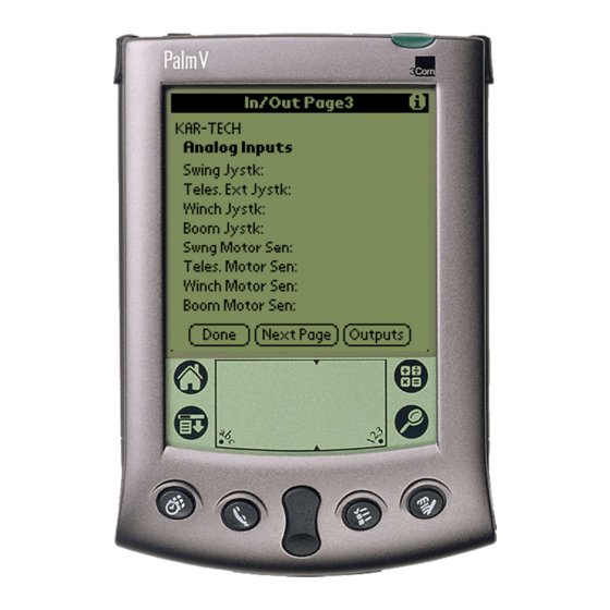
CAN RANGER OPERATION USING THE OPTIONAL PALM™ INTERFACE Patented Palm Pilot™ interface, patent 6,907,302, software is a very useful tool for troubleshooting the control system. To use this tool, connect the Palm™ serial cable to the serial connector Main Page... - Page 33 CAN RANGER OPERATION RF Communications Page Digital Inputs Page Tap the Next Page button to When the round circle next to switch between pages label dark, inputs. corresponding ON/OFF input or output is sensed to be active or ON.
- Page 34 CAN RANGER OPERATION button labeled view output Outputs screens. Digital Inputs Page 2 ON/OFF Outputs Page Analog Inputs Page...
-
Page 35: Histogram
CAN RANGER OPERATION Motor Output Page Histogram Page 1 Tap the Done icon return to This feature can be used to the main menu page. troubleshoot machine wiring and other problems. Tapping HISTOGRAM the Reset button resets the Tap the Histogram icon to see... -
Page 36: File Transfer
CAN RANGER OPERATION FILE TRANSFER CALIBRATION File Transfer To change the configuration of button to send new program the actuator outputs, tap the files from the Palm to the Calibration icon. receiver. New programs are uploaded to the Palm via the Palm™... - Page 37 CAN RANGER OPERATION Automatic configuration from the second drop- actuator positions is outlined down menu Kar-Tech 3. Enter the new value on INSTALLATION manual. line above Factory Setting button by tapping on the line and using the scratch pad to enter a new value 4.
- Page 38 CAN RANGER OPERATION Calibration Parameters Menu send these Save settings to memory. Tap the Setting button to Factory return all outputs to standard values. Tap Done and Exit to quit configuration and return to the main menu.
-
Page 39: Receiver Pinout
CAN RANGER OPERATION RECEIVER PINOUT P1:12 PIN DEUTSCH DT15-12PA WIRE PIN# DESCRIPTION COLOR* RPM+ GRAY GREEN RPM- GRAY HORN TILT UP OUTPUT (OPTIONAL) TILT DOWN OUTPUT (OPTIONAL) YELLOW ENGINE START WHITE ENGINE STOP PURPPLE WINCH SPEED ATB INPUT (OPTIONAL) OVERLOAD INPUT (OPTIONAL) -
Page 40: Wiring Block Diagram
CAN RANGER OPERATION WIRING BLOCK DIAGRAM LOCAL/RADIO R LOCAL/RADIO R BLACK - GROUND WHITE STOP RELAY WHITE YELLOW - START REMOTE GREY - HORN PURPLE - WINCH SPEED RED - POWER TELESCOPE ACTUATOR SWING ACTUATOR RECEIVER BOOM ACTUATOR WINCH ACTUATOR... -
Page 41: Wiring Schematic
CAN RANGER OPERATION WIRING SCHEMATIC... -
Page 42: Routine Maintenance
CAN RANGER OPERATION should be closely followed in ROUTINE MAINTENANCE carrying out any maintenance work. Clean transmitter regularly with a damp cloth and mild Do not have hydraulic power detergent. available to the valves when performing electrical tests. Inspect electrical wiring for wear points or other damage. -
Page 43: Troubleshooting
CAN RANGER OPERATION TROUBLESHOOTING This next section provides basic operator level troubleshooting for the CAN RANGER REMOTE system. If, after following these instructions, the system still does function, contact your KAR-TECH representative further instructions or servicing. -
Page 44: Troubleshooting Chart
CAN RANGER OPERATION TROUBLESHOOTING CHART PROBLEM SOLUTION 1. No functions work Check that transmitter power is Check that receiver power is on Check system wiring for power into the system Check status display system status Check for proper grounding of... - Page 45 CAN RANGER OPERATION TROUBLESHOOTING CHART PROBLEM SOLUTION 3. Functions operate Check for Loose connections. intermittently Check status display system status Check receiver antenna for any damage and proper connection Check system's hydraulic system 4. Engine stops while Check actuator feedback sensor.
-
Page 46: Parts List
Return the units for service. Note: For operation with negative ground systems only. WARNING: The CAN RANGER REMOTE must be operated in compliance with all applicable safety regulations, rules, and practices. Failure to follow required safety practices may result in death or serious injury. -
Page 47: Transmitter Pictorial
CAN RANGER OPERATION TRANSMITTER PICTORIAL AUTO NORMAL MANUAL SLOW E-STOP BASKET LEVELING WINCH BOOM EXTEND DOWN LOWER ENABLE ENABLE RETRACT RAISE TELESCOPE WINCH SWING BOOM WARNING PRESS E-STOP SWITCH TO CHECK E-STOP SWITCH FUNCTIONALITY BEFORE EACH JOB. PRESSING E-STOP SWITCH STOPS THE ENGINE IN CASE OF ELECTRICAL OR HYDRAULIC FAILURES. -
Page 48: Receiver Pictorial
CAN RANGER OPERATION RECEIVER PICTORIAL 8.74 2.63 REAR MOUNTING HOLES 8.24 8.91 ANALOG OUT -12 1- RPM+ USER ASSIST DISPLAY 2- RPM - ANALOG RPM -11 PAGE UP TILT DN IN -10 3- HORN TILT UP IN -9 4-TILT UP... -
Page 49: Actuator Pictorial
CAN RANGER OPERATION ACTUATOR PICTORIAL KAR-TECH INC. KAR-TECH INC. CAUTION! CAUTION! www.kar-tech.com www.kar-tech.com DO NOT ROTATE OUTPUT ROD, AS DO NOT ROTATE OUTPUT ROD, AS 1A0014B 1A0014B INTERNAL DAMAGE TO ACTUATOR INTERNAL DAMAGE TO ACTUATOR MAY OCCUR. USE FLATS PROVIDED FOR MAY OCCUR. -
Page 50: Specifications
CAN RANGER OPERATION SPECIFICATIONS P4U-VRTS FCC ID: Industry Canada Certification Number: 4534A-VRTS EQUIPMENT CLASS: PART 15 SPREAD SPECTRUM TRANSMITTER TRANSMITTER Power supply ....... 7.2 Volt Rechargeable, NiMH battery. Operating temperature - Radio ......-40˚C to +85˚C Storage temperature ........-40˚C to +100˚C RF Frequency ............ -
Page 51: Instruction To The User
CAN RANGER OPERATION INSTRUCTION TO THE USER This equipment has been tested and found to comply with the limits for a class B digital device, pursuant to part 15 of the FCC Rules. These limits are designed to provide reasonable protection against harmful interference in a residential installation. - Page 52 CAN RANGER OPERATION Appendix A USE THE FOLLOWING INSTRUCTION TO REMOVE DRAIN PLUGS TO ALLOW MOISTURE TO EXIT OR INSTALL DRAIN PLUGS WHERE FLUIDS CAN ENTER THROUGH THE DRAIN HOLES. SHIELD DRAIN HOLES IF IT IS DIRECTED WHERE FLUIDS CAN BE FORCED IN.
- Page 53 CAN RANGER OPERATION Appendix A WHEN MOUNTING WITH SHAFT HORIZONTAL AND CABLE UP, INSTALL ONE DRAIN PLUG AS SHOWN GROUND WHEN MOUNTING WITH SHAFT UP, REMOVE DRAIN PLUG WHICH IS NOT IN DIRECTION OF WATER GETTING FORCED IN. KAR-TECH INC.
- Page 54 CAN RANGER OPERATION Appendix B CRANE MANUFACTURER CRANE MODEL CRANE SERIAL NUMBER Factory setting New setting SWING CCW FAST POSITION SWING CCW SLOW POSITION SWING CCW ENGINE STOP POSITION SWING CENTER SWING CW ENGINE STOP POSITION SWING CW SLOW POSITION...
- Page 55 CAN RANGER OPERATION ENGINE CALIBRATION ENGINE CUMMINS MINIMUM RPM (Idle) 0.6 V MAXIMUM RPM (Full throttle) 3.8 V FREQUENCY...
Need help?
Do you have a question about the CAN RANGER and is the answer not in the manual?
Questions and answers