Table of Contents
Advertisement
Quick Links
Advertisement
Table of Contents

Related Manuals for Melchor Varela SARK-110

Summary of Contents for Melchor Varela SARK-110
- Page 1 SARK SARK- - - - 110 SARK SARK Vector Impedance Antenna Analyzer User’s Manual Revision 0.7 Updated to Firmware Version 0.6.x This document is licensed under a Creative Commons Attribution-NonCommercial-ShareAlike 3.0 Unported License. © Melchor Varela – EA4FRB 2011-2012...
-
Page 2: Table Of Contents
APPENDIX B: UPDATING THE FIRMWARE .................31 APPENDIX C: OSL CALIBRATION ..................32 APPENDIX D: DETECTOR CALIBRATION................35 APPENDIX E: SCALE PRESETS ...................38 APPENDIX F: CALIBRATION LOADS MANUFACTURING ..........40 Rev 0.7 Sept 3 , 2012 - 2 - © Melchor Varela – EA4FRB 2011-2012... -
Page 3: Introduction
The SARK-110 features a Direct Digital Synthesis (DDS) generator with a range of 0.1 to 230 MHz and a frequency resolution of 1 Hz. The instrument has full vector measurement capability and accurately resolves the resistive, capacitive and inductive components of a load. -
Page 4: Features
Export data in ZPLOTS compatible format for further analysis on the PC • Lifetime free firmware upgrades available, open to community requested features • Open source SDK including a device simulator for user applications development Rev 0.7 Sept 3 , 2012 - 4 - © Melchor Varela – EA4FRB 2011-2012... -
Page 5: Operating The Sark-110
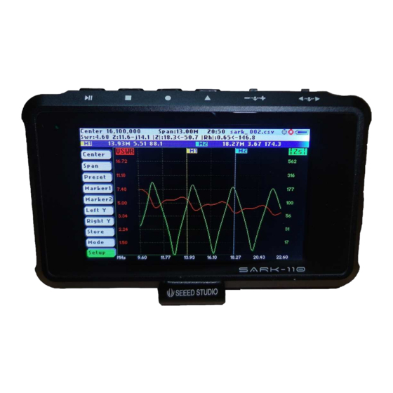
The following figure shows the screen layout in antenna test operating mode. It shows diagram areas that are the same for all operating modes of the SARK-110. Screen layouts that show specifics for each operating mode are provided in the corresponding sections of this manual. -
Page 6: Means Of Input
Center, Span, Marker1, Marker2, LeftY and RightY) and to navigate in the pop-up submenus. Run/Hold [►||] The button Run/Hold is used to control the operation state of the SARK-110: Working or Pause. In the pause state the signal generator and measurement circuits are disabled. -
Page 7: Changing The Center Frequency
Navigator A. The span is validated by pressing the button Select [■].The setting could be cancelled by pressing any other button. Rev 0.7 Sept 3 , 2012 - 7 - © Melchor Varela – EA4FRB 2011-2012... -
Page 8: Frequency Presets
The Navigator B is used to navigate the desired option. The selection is validated by pressing the button Select [■]. Pressing any other button will cancel the setting. Rev 0.7 Sept 3 , 2012 - 8 - © Melchor Varela – EA4FRB 2011-2012... -
Page 9: Using Markers
SARK 3.6 Using Markers The SARK-110 has two markers that can be either manually positioned by the user or operate in an automatic tracking mode. The markers indicate the horizontal and vertical position of the point they are positioned on. The horizontal position of a marker is shown by a dotted vertical line which extends from the top to the bottom of the measurement diagram. - Page 10 Rev 0.7 Sept 3 , 2012 - 10 - © Melchor Varela – EA4FRB 2011-2012...
-
Page 11: Changing Vertical Axis Parameter
Z at 50-ohm: 3.7 Changing Vertical Axis Parameter The SARK-110 in the antenna test mode is able to display two traces from any of the available parameters for the vertical axis. There are two methods to change the parameter, either by pressing the button Select [■] to activate the pop-up parameters list box or by using the... -
Page 12: Saving And Recalling Measurements
3.8 Saving and Recalling Measurements The SARK-110 has the capability to store the measurements to the internal disk and recall them either to review the data later in the analyzer screen or to be recovered from the USB disk to be further analyzed by the ZPLOTS Excel application available at http://www.ac6la.com/zplots.html. - Page 13 The Navigator B will be used to navigate the files and the button Select [■] to delete the file. When selecting the «Delete All» option all user files will be deleted. A confirmation dialog box will be activated to prevent the accidental deletion. Rev 0.7 Sept 3 , 2012 - 13 - © Melchor Varela – EA4FRB 2011-2012...
-
Page 14: Taking Screenshots
The analyzer provides different operating modes. The operating mode pop-up list box is activated by pressing the button Select [■] when the «Mode» option is active; see screenshot below: Rev 0.7 Sept 3 , 2012 - 14 - © Melchor Varela – EA4FRB 2011-2012... -
Page 15: Changing The Settings
Select [■]. Pressing any other button will cancel the selection. 3.11 Changing the Settings The configuration menu provides access to several setup options of the SARK-110. The setup pop-up list box is activated by pressing the button Select [■] when the «Setup» option is active;... - Page 16 This setting allows programming the automatic power off feature according a set of predefined values. After power-off the analyzer operation can be resumed by either pressing the button Select [■] or powering-off and powering-on using the Power Switch. Rev 0.7 Sept 3 , 2012 - 16 - © Melchor Varela – EA4FRB 2011-2012...
- Page 17 WWV. When exactly 10 MHz output is obtained, press the button Select [■] to permanently store the setting. It will be possible to get back to the default setting by pressing [●]. Rev 0.7 Sept 3 , 2012 - 17 - © Melchor Varela – EA4FRB 2011-2012...
- Page 18 The Reset Factory Defaults options allow resetting the analyzer to the default settings. Setup - About The about screen displays copyright information, the release information of the analyzer firmware and the disk space information. Rev 0.7 Sept 3 , 2012 - 18 - © Melchor Varela – EA4FRB 2011-2012...
-
Page 19: Antenna Test Mode
Run/Hold [►||]. In this case the results of the measurements are kept in the internal memory and plotted in the display to allow the user analysis. The Rev 0.7 Sept 3 , 2012 - 19 - © Melchor Varela – EA4FRB 2011-2012... -
Page 20: Smith Chart Mode
Smith Chart diagram. As in the Antenna Test mode, the measurements are performed continuously unless it is stopped by pressing the button Run/Hold [►||]. Rev 0.7 Sept 3 , 2012 - 20 - © Melchor Varela – EA4FRB 2011-2012... -
Page 21: Single Frequency Mode
Detailed measurements extended capacitance Parallel impedance complex form Reference impedance setting Circuit equivalent parallel Calibration status Parallel resistance and equivalent Run/Hold status capacitance Frequency setting USB/Battery status Rev 0.7 Sept 3 , 2012 - 21 - © Melchor Varela – EA4FRB 2011-2012... - Page 22 In this mode the analyzer can be used as a precision signal generator since a continuous signal at the selected frequency is outputted at the test port. Rev 0.7 Sept 3 , 2012 - 22 - © Melchor Varela – EA4FRB 2011-2012...
-
Page 23: Cable Test Mode
The impulse response trace (red trace) gives an indication of the location of the fault. The step response trace (green trace) provides an indication about the cause of the fault. Rev 0.7 Sept 3 , 2012 - 23 - © Melchor Varela – EA4FRB 2011-2012... - Page 24 Positive peak Resistor R < Z Negative level shift Negative peak Inductor Positive peak Positive then negative peaks Inductor Negative peak Negative then positive peaks Rev 0.7 Sept 3 , 2012 - 24 - © Melchor Varela – EA4FRB 2011-2012...
-
Page 25: Specifications
• Display all parameters for a single frequency Single Frequency Mode • Presets for radio amateur bands • Graphical representation of series and parallel impedance equivalent Rev 0.7 Sept 3 , 2012 - 25 - © Melchor Varela – EA4FRB 2011-2012... - Page 26 • 256 calibration points • Calibration settings stored in disk • Frequency calibration • Single conversion superheterodine Measurement Architecture • Two independent measurement channels for simultaneous voltage Rev 0.7 Sept 3 , 2012 - 26 - © Melchor Varela – EA4FRB 2011-2012...
- Page 27 Dimensions Weight 300g • SARK-110 x 1 Pack List • Battery x 1 • MCX to BNC adapter pigtail x 1 • Screwdriver x 1 Rev 0.7 Sept 3 , 2012 - 27 - © Melchor Varela – EA4FRB 2011-2012...
-
Page 28: Precautions
4. This product emits a low power RF signal during the active measurement mode. When connected to an antenna system, it may cause interference to nearby communication systems. Connect only for as long is necessary. Rev 0.7 Sept 3 , 2012 - 28 - © Melchor Varela – EA4FRB 2011-2012... -
Page 29: Acknowledgments
Operation of this equipment in other environments may cause interference with radio communications, in which case, the user is required to take whatever measures may be required to correct this interference his own expense. Rev 0.7 Sept 3 , 2012 - 29 - © Melchor Varela – EA4FRB 2011-2012... -
Page 30: Appendix A: Fundamental Parameters
Return Losses Return loss is the negative of the magnitude of the reflection coefficient in dB. × = Rho × %RPwr Percentage of RPwr Reflected Power Rev 0.7 Sept 3 , 2012 - 30 - © Melchor Varela – EA4FRB 2011-2012... -
Page 31: Appendix B: Updating The Firmware
Appendix B: Updating the firmware The firmware of the SARK-110 is upgradeable via USB as described in the following steps: 1. Connect the SARK-110 to the PC with an USB cable 2. Copy the firmware file, e.g. SARK110-VAA-APP.dfu to the USB disk 3. -
Page 32: Appendix C: Osl Calibration
Appendix C: OSL Calibration The SARK-110 provides a calibration procedure to compensate the stray capacitance and impedance of the external test fixture, e.g. the extension cable. This should be performed every time the external test fixture is changed and periodically. - Page 33 The calibration progress will be shown in the display bar. Connect the reference load. Press the button [■] to continue, or the button [▲] to cancel. Rev 0.7 Sept 3 , 2012 - 33 - © Melchor Varela – EA4FRB 2011-2012...
- Page 34 The calibration progress will be shown in the display bar. Press the button [■] to apply the calibration settings, or the button [▲] to cancel. Rev 0.7 Sept 3 , 2012 - 34 - © Melchor Varela – EA4FRB 2011-2012...
-
Page 35: Appendix D: Detector Calibration
SARK Appendix D: Detector Calibration This procedure performs the aligment of the SARK-110 internal measurement circuits. This operation is done once at the factory and it is not necessary that the user do this operation but this is provided anyhow. - Page 36 Press the button [■] to continue, or the button [▲] to cancel. Connect the 200-ohm load. Press the button [■] to continue, or the button [▲] to cancel. Rev 0.7 Sept 3 , 2012 - 36 - © Melchor Varela – EA4FRB 2011-2012...
- Page 37 The calibration coefficients are shown in bottom part screen information. Press the button [■] to apply the calibration settings, or the button [▲] to cancel. Rev 0.7 Sept 3 , 2012 - 37 - © Melchor Varela – EA4FRB 2011-2012...
-
Page 38: Appendix E: Scale Presets
Linear Linear Theta Linear Phase -180 Linear Linear Linear High: Scale 1.00 99.00 2000 2000 -500 Linear Linear Theta Linear Phase -180 Linear Linear Linear Rev 0.7 Sept 3 , 2012 - 38 - © Melchor Varela – EA4FRB 2011-2012... - Page 39 User’s Manual SARK SARK- - - - 110 SARK SARK Low: Scale 10.0 -250 Linear Linear Theta Linear Phase -180 Linear Linear Linear Rev 0.7 Sept 3 , 2012 - 39 - © Melchor Varela – EA4FRB 2011-2012...
-
Page 40: Appendix F: Calibration Loads Manufacturing
Part Part number Source Description BNC Connector 171-9311 Mouser BNC Plug Solderless W/Strain Relief R 100-Ohm P100DACT-ND DigiKey RES 100 OHM 1/8W .1% 0805 SMD Rev 0.7 Sept 3 , 2012 - 40 - © Melchor Varela – EA4FRB 2011-2012... - Page 41 Open: Part Part number Source Description BNC Connector 171-9311 Mouser BNC Plug Solderless W/Strain Relief Not required N.R. Just leave the connector as it is Rev 0.7 Sept 3 , 2012 - 41 - © Melchor Varela – EA4FRB 2011-2012...
Need help?
Do you have a question about the SARK-110 and is the answer not in the manual?
Questions and answers