Table of Contents
Advertisement
Quick Links
Advertisement
Table of Contents

Related Manuals for Avante Alta V10

Summary of Contents for Avante Alta V10
- Page 2 Preface Read carefully and understand the contents of this manual before using this equipment. Intellectual property rights The company owns the intellectual property rights of this product, this manual must be treated as confidential information. This manual only provides references for the operation, maintenance and repair of our products.
- Page 3 ◆ IEC 60601-1 applies to all medical electrical equipment used or part of the Anesthetics machine in question. Even if the individual components in the device are non-functional when they are connected to an auxiliary power outlet that forms the medical electrical system. The operator must be aware that when the device is connected to the auxiliary power outlet current leakage is an evaluated risk.
- Page 4 When this system is shipped back for maintenance, users should bear the freight (including customs fees). Equipment life: 8 years Company Address Company: Avante Health Solutions Address: 2601 Stanley Gault Pkwy Suite 101, Louisville, KY 40223 Tel: (502) 244-4444 Revision History This manual has a revision number.
-
Page 5: Table Of Contents
Table of Contents Chapter 1 Safety 1.1 System Safety 1.1.1 System Terms 1.1.2 Warning 1.1.3 Caution 1.1.4 Caution 1.2 Equipment Symbols 1.3 Term abbreviation and definition 1.4 System information 1.4.1 System classification 1.4.2 Device standards 155 1.4.3 Integral system components Chapter 2 Overview 2.1 Introduction 2.1.1 Intended use... - Page 6 Chapter 4 Pre-Operative Test 4.1 Pre-Operation Test Procedure 29 4.1.1 Test interval 4.2 System Check 4.3 Flow control system test 30 4.4 Oxygen flush test 4.5 Vaporizer test 4.5.1 Vaporizer back pressure test 4.5.2 Vaporizer interlock system test 4.6 APL Valve Test 31 4.7 Alarm test 4.7.1 Prepare for alarm test 4.7.2 Minute volume(MV) low alarm test...
- Page 7 6.4 Standby Mode 6.4.1 Enter Standby Mode 6.4.2 Exit Standby Mode 6.5 Set Ventilation Mode 6.5.1 Volume Control Ventilation(VCV) 37 6.5.1.1 Description 6.5.1.2 Start VCV Mode 38 6.5.1.3 Parameter Setup Area in VCV Mode 38 6.5.1.4 Set Parameters in VCV Mode 38 6.5.2 Pressure Control Ventilation(PCV) 6.5.2.1 Description 6.5.2.2 Start PCV Mode 40...
- Page 8 6.7.2.1 Waveform 6.7.2.2 Parameter Monitoring 50 6.7.3 Modes Menu 6.7.4 Control Menu 6.7.5 Monitoring Menu 51 6.7.6 Alarms Menu 6.7.6.1 Alarm limits 1 6.7.6.2 Alarm limits 2 6.7.6.3 Alarm log 6.7.7 System Menu 6.7.7.1 Information Menu 6.7.7.2 Setup Menu 6.7.7.2.1 Set Alarm loundness 56 6.7.7.2.2 Set Language 57 6.7.7.2.3 Set Units 6.7.7.2.4 Sensor on/off 57...
- Page 9 7.3.8 Set pressure support level 7.3.9 Set Apnea time 7.3.10 Set inspiratory pause 7.3.11 Set Rise Time 7.3.12 Set Expiratory trigger sensibility 62 7.4 Start To Mechanical Ventilation 62 7.5 Parameters Monitoring 62 7.5.1 FiO monitoring 7.5.2 Pressure Monitoring 7.5.3 Tidal Volume Monitoring 63 7.5.4 Breath Rate Monitoring 7.5 Pulmonary function 7.6 Alarm setup...
- Page 10 9.3.6 Re-install the absorber canister 72 9.3.7 Re-Install the flow sensor 72 Chapter 10 User Maintenance 10.1 Maintenance Policy 10.2 Maintenance Schedule 74 10.3 Pressure Sensor Zeroing 10.4 Flow Sensor Zeroing 10.5 Oxygen concentration calibration 10.5.1 21% O Calibration 10.5.2 100% O calibration 10.6 Touchscreen Calibration 10.7 Fault Diagnosis and Troubleshooting 75...
-
Page 11: Chapter 1 Safety
Chapter 1 Safety 1.1 System Safety 1.1.1 System Terms User’s manual warnings, cautions, and important issues. Danger Indicates risk – harm for the patient or serious consequences, as well as serious damage to property caused by vigilant operation. Warning ◆... -
Page 12: Caution
⚫ Electromagnetic field anesthetics workstation performance would adversely affect the use of other devices in the vicinity. Pay attention to the relevant EMC requirements. Mobile phones, MRI equipment, X-ray emitted electromagnetic radiation can impact device and cause interference. ⚫ Assure that the local power supply voltage and frequency are consistent with the requirements of this equipment. -
Page 13: Equipment Symbols
1.2 Equipment Symbols Alternating current Fuse General warning (yellow Dangerous voltage background) Type BF equipment Type B equipment Battery Equipotential AC power supply Battery symbol (indicating the (Indicates a connection to battery status, display the mains) current remaining capacity) Power On Power Off Lighting USB interface... - Page 14 The logo appears do not touch Caution the interface Identifies the user needs to Do not reuse perform the operation Refer to instruction manual Operating instructions Date Of Manufacture Manufacturer Authorized Representative In Serial Number The European Community Batch Code Catalogue Number CE marking and Notified Protected against solid foreign...
-
Page 15: Term Abbreviation And Definition
Home position Absorbent bypass on 1.3 Term abbreviation and definition Abbreviation Definition Anesthetics agent AGSS Anesthetics Gas Scavenging System ACGO Auxiliary Common Gas Outlet Adjustable Pressure Limit BTPS Body temperature, ambient pressure, saturated humidity conditions Breath Delivery Unit Cdyn Dynamic Compliance Carbon dioxide Desflurane Enflurane... - Page 16 fspn Spontaneous respiratory rate Fsens Flow Trigger Sensibility Graphic User Interface Halothane Inspiratory-expiratory ratio Insp Inspiratory Isoflurane L/min L/min kilopascal Kilogram Minimum alveolar concentration Manual Manual ventilation Minute volume Nitrous oxide Oxygen Airway pressure Pressure control ventilation PEEP Positive end-expiratory pressure Pinsp Pressure control level of inspiration Plimit...
-
Page 17: System Information
Texp Expiratory time Tidal volume Expired tidal volume Inspired tidal volume Volume control ventilation 1.4 System information 1.4.1 System classification This system is classified as follows: Class I Equipment. Type B Equipment. Type BF Equipment. Continuous operation. 1.4.2 Device standards Devices used with this Anesthetics system shall comply with the following standards where applicable: Breathing system and breathing system components ISO 80601-2-13. - Page 18 ■ Oxygen Sensor ■Side stream CO module ■IRMA CO /AX+ module ■ SpO module ■Auxiliary Common Gas Outlet(ACGO) ■Anesthetics vapor delivery device. ■Anesthetics gas scavenging systems(AGSS) ■Auxiliary Oxygen ■Suction regulator ■ Driver gas switch valve...
-
Page 19: Chapter 2 Overview
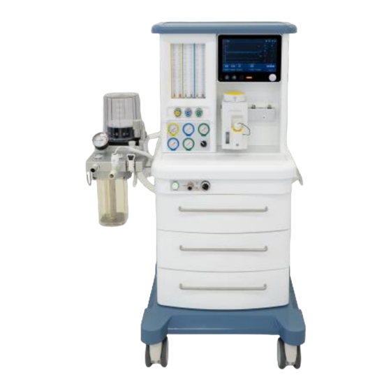
Chapter 2 Overview 2.1 Introduction 2.1.1 Intended use The Anesthetic machine is intended to provide breathing Anesthetics for adult, pediatric patients during surgery. The Anesthetics machine must only be operated by qualified anesthesia personnel who have received the correct training for its use. The anesthesia machine without absolute contraindications. - Page 20 Front view Frame Anesthesia Vaporizer with Mounting bar Anesthesia Ventilator Handle Drawers Castors ACGO switch ◼ When ACGO switch is on: Fresh gas will be delivered to half open breathing system through ACGO outlet. ◼ When ACGO switch is off: Fresh gas will be delivered to CO2 Circle Absorber.
- Page 21 ACGO port Soda lime chamber 10. CO2 Circle Absorber 11. Airbag port 12. Bellow 13. Pipeline gas pressure gauges Displays the pressure value of the pipelines gas or the regulated pressure value of reserve cylinder gas. 14. Fresh gas flowmeter Fresh gas flow control knob ◼...
- Page 22 Auxiliary electrical outlets( 3 outlets on back) Fuse Mains inlet AGSS connection Fresh Gas outlet Driving gas Flow sensor connector...
-
Page 23: Anesthesia Ventilator
Arm for CO2 Circle Absorber O2 sensor connector 10. N2O gas source inlet 11. O2 gas source inlet 12. Pole for cable 13. Fan 14. Communication port 15. Battery box cover Communication port A. Calibration port (attachment to connect external calibration equipment for the machines calibration. -
Page 24: Battery Indicator 223
One set of batteries About 4 hours About 90 minutes Caution ⚫ If a battery has been discharged and has been stored for a long time, charging may take longer than the time stated in the table above. 2.4.1 Battery indicator On-screen the power status indicator as follows: : The AC power is being used. - Page 25 machine. Install the battery to the battery compartment as shown in the figure above. Install the battery cover. Replacing batteries: Replace batteries with reference to installing batteries.
-
Page 26: Chapter 3 Installation And Connections
Chapter 3 Installation and Connections Warning ◆ To ensure that pipeline gas supply hose and breathing circuit components are not toxic, and will not cause allergic reactions to the patient and does not react with the anesthetic substances. ◆ Continuous use of desiccated soda lime may endanger patient safety. Adequate precautions should be taken to ensure that the soda lime in the absorber canister does not become desiccated. -
Page 27: Install The Oxygen Sensor
5.Install the soda lime chamber on the down of metal body Insert the soda lime chamber. 3.2 Install the Oxygen Sensor Warning ◆ Before installing the O sensor, check that the seal on the sensor is in good condition. Fit a new sensor if the seal is missing or damaged. -
Page 28: Power Connector
⚫ The blue Flow Sensor tube must be toward the patient. ⚫ The Flow Sensor tubes must be upright. ⚫ The Flow Sensor tubes must not be kinked. ⚫ The Flow Sensor tubes must be secured with clamp (included with Flow Sensor). 3.5 Installation of the Manual Bag Connect the breathing bag to the manual bag port on the CO2 Circle Absorber system. -
Page 29: Connect The Pipeline
3.9 Connect the pipeline Connect the pipeline among CO2 circle absorber, bellow and the body of anesthesia machine. -
Page 30: Chapter 4 Pre-Operative Test
Chapter 4 Pre-Operative Test 4.1 Test procedure before the operation 4.1.1 Test Interval In the following cases, the test should be performed before the operation: 1) preoperative test should be initiated in each patient before the operation. 2) When required after a maintenance or service procedure. Recommended testing schedule is as follows:... -
Page 31: Flow Control System Test
Applicable Anesthetics and emergency drugs are available. The casters are not damaged or loose and the brakes are set and function correctly. 10. Make sure the breathing system is locked in position. 11. The AC main indicator and the battery indicator come on when the power cord is connected to an AC power source. -
Page 32: Oxygen Flush Test
4.4 Oxygen Flush Test Connect O pipeline. Set the system switch to the position. Ensure that the bag/Vent switch is set to vent position. Connect the patient circuit and seal the Y-piece by test block. Push the O flush button, Check that the bellows fully inflate within 4 seconds. Release the O flush button to stop inflation. -
Page 33: Apl Valve Test
4.6 APL Valve Test Set the system switch to the position. Ensure that the bag/Vent switch is set to bag position. Check that the breathing bag and breathing tubes are correctly connected. Connect the Y-piece to the test plug on the breathing system. Adjust APL valve limited pressure. -
Page 34: Pressure High Alarm Test
2. Check that a MV low alarm is triggered. 3. Set the MV low alarm limit to 2.0 L/min and check that the alarm is cancelled. 4.7.3 PRESSURE HIGH Alarm Test 1. Set the pressure high alarm limit to 30cmH 2. - Page 35 8. Turn all flow controls to set all gas flows to minimum. 9. Check that the breathing system is not damaged and correctly connected. Warning ◆ Before connecting a patient, flush the Anesthetic machine with 5 L/min of O for at least one minute.
-
Page 36: Chapter 5 Basic Operation
Chapter 5 Basic Operation 5.1 Turn on the System Plug the power cord into an AC mains power outlet. The mains indicator is lit when the AC power is connected. The battery will be charged (if it is not already fully charged). Check that the breathing system is properly connected. -
Page 37: Sign Breath Internal
5.5.3 Sign Breath Internal Select the [System] -> [Settings] -> [Sigh Breath Every]. In the [Sigh Breath Every] menu, set 50-100 breaths. 5.5.4 Set the Language Select the [System] -> [Settings] -> [Language]. In the [Language] menu, select the required language. 5.5.5 Set O monitoring switch If the anesthetic machine is not configured with an O... -
Page 38: Chapter 6 Anesthesia Ventilator
Chapter 6 Anesthesia Ventilator 6.1 Set up 1. Connect the machine to the AC Power. 2. Connect the machine to the pressure gases (280 - 600 kPa). 3. Assemble the breathing system and bellows with anesthesia machine. 4. Connect the flow sensor and oxygen sensor etc. WARNING ⚫... -
Page 39: Standby Mode
FIGURE 6-1 patient setup 6.4 Standby Mode Standby Mode is the operating mode in which all the systems functionality are idle. It is the default system startup operating mode and is used between ventilation operations. During Standby, the user can adjust some settings in any ventilation mode, but no ventilation mode is enabled. 6.4.1 To Enter Standby Mode: 1. -
Page 40: Start Vcv Mode
FIGURE 6-2 flow and paw waveform in VCV mode decelerating flow by the flow pattern setting in the The ventilator can deliver constant flow or [controls] menu. Although patients may be safely ventilated utilizing a constant flow pattern, the decelerating flow pattern does provide other benefits in addition to minimizing pressures. -
Page 41: Pressure Control Ventilation(Pcv)
following takes setting of VT as an example. 1. Push the [VT] button. 2. turn control knob to set [VT] to the desired value. 3. Push the control knob or the [VT] button to confirm the setting. 4. Set other parameters in this mode in the similar way. FIGURE 6-4 All parameters in VCV mode 6.5.2 Pressure Control Ventilation (PCV) 6.5.2.1 Description... -
Page 42: Start Pcv Mode
FIGURE 6-5 The paw and flow waveforms in PCV mode Generally, in the PCV mode, the Paw waveform rises sharply during inspiration and stays at the plateau for a relatively long time without peak. The flow waveform declines in the same period. -
Page 43: Pressure Regulated Volume Control(Prvc)
FIGURE 6-7 All parameters in PCV mode 6.5.3 Pressure Regulated Volume Control (PRVC) 6.5.3.1 Description PRVC is a controlled mode of ventilation which combines the advantages of volume controlled and pressure-controlled ventilation. The ventilator delivers the preset tidal volume with the lowest possible pressure. -
Page 44: Start Prvc Mode
1. Push the [Modes] button to open the [Modes] menu. 2. Push [PRVC] in the [Modes] menu, then the [controls] menu for PRVC mode is opened. 3. Adjust appropriately parameter settings for the patient and then confirm the settings so as to start PRVC mode. -
Page 45: Start Psv Mode
Pressure Support is a spontaneous mode of ventilation. The patient initiates the breath and the ventilator delivers support with the preset pressure level. With support from the ventilator, the patient also regulates the respiratory rate and the tidal volume. In Pressure Support, the patient triggers all breaths, the preset inspiratory Pressure Support level is kept constant and there is a decelerating flow. -
Page 46: Set Parameters In Psv Mode
When PSV mode is confirmed, Key parameters is automatically switched over to the parameter setup area in this mode. It is convenient to monitor and set. The following figure shows these parameters to be set in PSV mode. FIGURE 6-12 Key parameters in PSV mode 1. -
Page 47: Start Simv Mode
respiratory pattern and volumes/pressures).The SIMV rate is the rate of the mandatory breaths per minute. The spontaneous/pressure-supported breath is defined by setting the Pressure Support level above PEEP. When the user gradually decreases the SIMV rate, the patient has more and more time for the spontaneous/pressure-supported breaths. - Page 48 FIGURE 6-15 Key parameters in SIMV-VC mode 1. [VT]: Tidal volume 2. [Ti]: Inspiratory time 3. [Rate]: Breath rate 4. [Psupp]: Pressure support level above PEEP 5. [PEEP]: Positive end-expiratory pressure 6. [Psens] or [Fsens] Pressure trigger sensitivity or flow trigger sensitivity ⚫...
-
Page 49: Set Parameters In Simv Mode
5. [PEEP]: Positive end-expiratory pressure 6. [Psens] or [Fsens] Pressure trigger sensitivity or flow trigger sensitivity 6.5.5.4 Set Parameters in SIMV Mode The same method as 4.5.1.4 Figure 6-18 All parameters in SIMV-VC mode Figure 6-19 All parameters in SIMV-PC mode... -
Page 50: Manual/Spontaneous Mode
Figure 6-20 All parameters in SIMV-PRVC mode 6.5.6 Manual/Spontaneous Mode Manual/spontaneous ventilation mode is the operating mode used for manually ventilating a patient or to let a patient breathe spontaneously. To use the manual/spontaneous ventilation mode, the user must first set the APL valve in breath system to the appropriate pressure value and then select MAN./SPONT mode from [modes] menu. -
Page 51: Normal Screen
Figure 6-21 Standby screen In standby status, the following changes occur to the system: ⚫ Displaying monitored parameters and waveforms is disabled. The system is in standby status. ⚫ The ventilator stops to deliver gases. ⚫ The parameters can be set. When the standby status exits, the system will operate based on the final settings in standby status. -
Page 52: Waveform
Figure 6-22 Normal screen 6.7.2.1 Waveform The waveform combinations vary depending on the configurations. The waveforms displayed include: ⚫ Paw waveform ⚫ Flow waveform ⚫ Volume waveform ⚫ CO2 waveform ⚫ Pleth waveform ⚫ Volume-Flow loop ⚫ Pressure-Flow loop ⚫ Pressure-Volume loop Push button to open or close spirometry loop display and push... -
Page 53: Control Menu
Figure 6-23 Modes screen 6.7.4 Controls Menu When pressing [Controls] button, the controls menu appears. The parameter combinations displayed vary in controls menu depending on mode setting. 6.7.5 Monitoring Menu When pressing [Monitoring] button, the monitoring menu appears. All monitoring parameters are displayed in this menu, two sub-menus are displayed. -
Page 54: Alarms Menu
Figure 6-25 Values 2 sub-menu in the monitoring menu 6.7.6 Alarms Menu When pressing [Alarms] button, the alarms menu appears. The alarms menu has three sub- menus: ⚫ Limits 1 ⚫ Limits 2 ⚫ Alarm log Activate the setting by pressing control knob or pressing desired setting button. Several alarm settings can be changed immediately, by turning the control knob, and press control knob or button to confirm. -
Page 55: Alarm Limits
Figure 6-26 Alarm limits 1 sub-menu The following alarm settings can be accessed in this menu: ⚫ High pressure ⚫ Low pressure ⚫ High MVexp (expiratory minute volume) ⚫ Low MVexp (expiratory minute volume) ⚫ High ftotal (respiratory rate) ⚫ Low ftotal (respiratory rate) ⚫... -
Page 56: Alarm Log
If the CO2 module or SpO2 modules are not installed, CO2/SpO2 alarm settings can not be set. WARNING The alarms should be adjusted according to the patient and should not be adjusted to extreme settings. 6.7.6.3 Alarm Log Two hundred recent alarms can be stored in the alarm log. If the alarm log is full, the oldest alarm record will be overwritten. -
Page 57: Setup Menu
⚫ Runtime (Ventilator Operating Hours) ⚫ Barometric Pressure ⚫ Gas supply Pressure When the option is installed, the option icon is active. The following figure shows the information sub-menu. Figure 6-29 Information menu 6.7.7.2 Setup Menu The following settings can be accessed in this menu: ⚫... -
Page 58: Set Language
6.7.7.2.2 Set Language Set the language as follows: Select the current language pop-up window opens. Select the desired language or push the control knob to confirm selection. After confirmation, the language for screen display is update automatically. 6.7.7.2.3 Set Units Set units as follows: Press [units] button to open units setting menu (Figure 6-31). -
Page 59: Calibration
YYYY]. Figure 6-32 Data & Time Menu 6.7.8 Calibration Touch the [Calibration] window (Figure 6-33) to view and access the calibrations. Figure 6-33 Calibration menu 6.7.8.1 Pressure Sensor Zero Calibration Touch [Pressure Sensor Zero] button, the calibration menu appears. Follow the instructions displayed, disconnect the breathing circuit at the patient side of the flow sensor, touch [Start] button. -
Page 60: O2 Cell Calibration
Completed!”. 6.7.8.3 O Cell Calibration NOTE: ⚫ The O cell calibration requires that an O cell be installed, monitoring enabled, and oxygen be available. Touch [O cell] button, the calibration menu appears. Follow the instructions displayed, disconnect the O sensor from breathing circuit, touch [100%] button or [21%] button respectively. -
Page 61: Chapter 7 Operation And Ventilation Setting
Chapter 7 Operation and Ventilation Setting Warning ◆ Before clinical use, check that all connections are secure and the pre-operation tests are completed. If any tests failed, do not use the system. Contact the service engineer for repair. 7.1 Input Fresh Gas 7.1.1 N O, O , Air Input Settings... -
Page 62: Set Ventilation Mode
7.2 Set Ventilation Mode 7.3 Ventilator Settings 7.3.1 Set Tidal Volume Select [VT] hotkey. 2) Press the control knob; turn the knob to set the required VT value. 3) Press the control knob to confirm and activate the change. Caution ⚫... -
Page 63: Set Pressure Control Level
7.3.7 Set Pressure Control Level 1) Select the [Pinsp] hotkey. 2) Press the control knob and turn the knob to set Pinsp at the desired value. 3) Press the control knob to confirm and activate the change. 7.3.8 Set Pressure Support Level 1) Select the [Psupp] hotkey. -
Page 64: Start To Mechanical Ventilation
7.4 Start Mechanical Ventilation To exit Standby mode and start mechanical ventilation, press the Standby key. Caution ⚫ Check the parameters are set to appropriate values before starting ventilation. 7.5 Parameters Monitoring 7.5.1 FiO monitoring If the system is configured with an O module or an oxygen sensor, FiO values are displayed. -
Page 65: Pulmonary Function
7.5 Pulmonary Function The system displays dynamic compliance monitoring, static resistance, and spirometry loops to reflect the patient’s pulmonary function. The system provides two spirometry loops: Paw-V (Paw-volume) loop and V- Flow (volume-flow) loop. The scales of volume flow and Paw are adjusted automatically. 7.6 Alarm Setup Use the Alarm setup menu to set and adjust alarm limits and to view alarm history. -
Page 66: Alarm
⚫ the alarm is added to the list of alarms in the alarm log. Only the highest priority alarm message is displayed in the alarm state area. If more than one alarm is activated, the icon is displayed. If the alarm condition is removed during this time, the alarm is automatically cleared from the list, but for the last alarm, the alarm message will continue until the silence key is pressed. -
Page 67: Alarm Message
Only play low black text yellow Yellow priority alarm sound background, low one time priority mark ! TABLE 8-1 Alarm indicators 8.5 Silencing Alarms When an alarm condition occurs and the alarm audio is sounded, the user can select the Silence key to silence the alarm audio. -
Page 68: Chapter 9 Cleaning And Disinfection
cycles. FiO2 low The oxygen concentration monitored value are High priority lower than the oxygen concentration lower limit set value for all continuous 10 respiratory cycles. Pulse rate high When pulse rate monitored value is higher than High priority pulse upper limit value for continuous 10 cycles. -
Page 69: Clean And Disinfect The Anesthetic Machine Housing
Warning ◆ Obey applicable safety precautions. ◆ Read the material safety data sheet for each cleaning agent. ◆ Read the operation and service manual for all disinfection equipment. ◆ Wear gloves and safety glasses. A damaged O sensor can leak and cause burns (contains potassium hydroxide). -
Page 70: Disassembling The Breath System
Caution ⚫ Use only soft dry and lint free cloth to clean the display. Do not use any liquid for display cleaning. 9.2 Disassembling the Breathing System You need to disassemble the breathing system cleanable parts first before cleaning the system. 9.2.1 Remove the oxygen sensor Take the O2 sensor from the 3 way connector. -
Page 71: Cleaning& Disinfection And Re-Install The Co2 Circle Absorber And Bellow
gas leakage. It’s dangerous to patient if the canister is not installed in a long time. 9.3 Cleaning& disinfection and Re-install the CO2 Circle Absorber and bellow Parts marked are autoclavable. Metal and glass parts can be steam autoclaved. Maximum commended temperature is 134ºC. -
Page 72: Re-Install The Co2 Circle Absorber
◼ Oxygen sensor: Clean with a damp cloth soaked in mild detergent and then wipe off the remaining detergent with a dry lint free cloth. ◼ Absorber canister assembly : First flush with water, then soak it in solution mixed by water and detergent 30 minutes, the suggested temperature is 30-41 ℃, after that treat by clean water, finally wipe by using 70% medical use alcohol or autoclave under maximum temperature 134℃. -
Page 73: Re-Install The Absorber Canister
2. Install the three way again and insert the O2 sensor on the it. 3. Install the oxygen sensor cable. 9.3.6 Re-install the Absorber Canister When the absorber canister is fully dry, install absorber canister on the CO2 circle absorber. 9.3.7 Re-Install the Flow Sensor Caution Flow sensor temperature will be heated to 35-40 º... -
Page 74: Chapter 10 User Maintenance
Chapter 10 User Maintenance 10.1 Maintenance policy Warning ◆ Only use lubricants approved for Anesthetic and O equipment. Do not use lubricants containing oil or grease that may burn or explode in high O concentrations. ◆ Follow infection control and safety procedures to prevent cross-infection. After clinical procedures, equipment may be contaminated with blood and body fluids. -
Page 75: Maintenance Schedule
10.2 Maintenance Schedule Caution ⚫ This schedule is based on a maximum total annual usage time of 2000 hours per year. If the actual annual usage exceeds 2000 hours, maintenance must be increased accordingly. ⚫ Local policies or regulations may require that maintenance be performed more frequently than stated here. -
Page 76: Flow Sensor Zeroing
In standby mode, touch the [System] hotkey -> [Calibration] hotkey ->[Pressure Sensor Cal]. Pressure sensor zero calibration will start automatically. 10.4 Flow Sensor Zeroing Stop manual or mechanical ventilation. If a breathing tube is connected to the breathing system, then open the breathing tube patient connection to air. Check that the bellows falls to the bottom. -
Page 77: 100% O
After a successful calibration, the screen shows [Calibration Completed!]. Otherwise the message [Calibration Failure! ] is displayed. In this case, you need to do the calibration again. 10.5.2 100% O calibration Caution ⚫ If the calibration fails, check for technical alarm. Then do the calibration again. ⚫... - Page 78 inflate completely expiratory time is too short. reasonable value The breathing system leaks Carry out a system leak test Flowmeter is closed Reset the flowmeter Bag/vent switch is still in the bag Turn the Bag/vent switch to vent position. During the in- Flow control valve has failed;...
-
Page 79: Chapter 11 Accessories
Chapter 11 Accessories Warning ◆ Use only accessories specified in this chapter. Using other accessories may cause incorrect measured valued or equipment damage. ◆ Disposable accessories can’t be reused. Reuse may degrade performance or cause cross- contamination. ◆ Check the accessories and their packages for damage. Do not use them if any sign of damage is detected. -
Page 80: Safety Standards
Product Specifications A.1 Safety Standards Type of protection against Class I, with internal power supply. electric shock When the integrity of the external protective earthing equipment or protective ground conductor generates doubt, the device must be replaced by: Internal power supply (battery). Type B: Breathing tubes. -
Page 81: Power Specifications
O Cut-off pressure Internal O supply pressure less than 90 kPa ACGO Connector Male 22 mm conical connector incorporating a coaxial female 15mm conical connector. Shared with inspiratory port. Fresh gas 6 tubes flowmeter range: 0 to 10 L/min O range: 0 to 12 L/min Air range: 0 to 15 L/min Accuracy: ±10% of reading value or ±... -
Page 82: Physical Specifications
Shortest supply time 90min; Charging time A.5 Physical Specifications Technical parameters Specification Machine Size 1370× 950 × 650 (H × W × D) Weight Approximately100kg Maximum bearing weight of the top 30kg cover Display Type Color TFTLCD (touch screen) Size 10.4 inches Resolution 800 ×... -
Page 83: Ventilator Specifications
Connector ACGO ports: standard OD 22mm, ID 15mm, tapered connector; Inhalation and exhalation ports: standard OD22mm, ID 15mm, tapered connector Manual bag port: standard OD22mm, ID 15mm, tapered connector System leaks In any mode, the system is not greaterthan140ml/min leakage System compliance Volume of gas lost due to internal compliance (Manual mode only): <3.0 ml/0.098 kPa (1 cmH... - Page 84 Pressure Trigger Range: 0 ~ 20 cmH2O; increments: 0.1 cmH2O. PSV Insp Termination Level Range: 5 ~ 80%; increments: 5%. monitored parameters Parameter Description Inspiratory tidal volume Range: 0 ~ 2500 mL; Resolution: 1 mL. Error of ± 20mL or actual value ±...
-
Page 85: Anesthetic Vaporizer(Optional)
Minute ventilation High 1 ~ 99 L 0 ~ 98 L Respiratory rate High 1 ~ 100bpm OFF,1 ~ 99 bpm FiO2(optional) High 19 ~ 100%, OFF 18 ~ 99% Airway pressure High 6 ~ 99 cmH2O 0 ~ 98 cmH2O SpO2(optional) High 50 ~ 100 %... -
Page 86: H Emc
H EMC Warning ◆ The devices need to be installed and used in compliance with the electromagnetic environment. ◆ Portable and mobile RF communications equipment can affect the equipment ◆ Pins of connectors identified with the ESD warning symbol should not be touched and connections should not be made to these connectors unless ESD precautionary procedures are used. - Page 87 8 kV air 8 kV air discharge (ESD) or ceramic tile. If floors are covered with synthetic material, IEC 61000-4-2 the relative humidity should be at least 30%. 2 kV for power supply 2kV for power Electrical fast Mains power quality should be lines supply lines transient/burst...
- Page 88 80 MHz~800 MHz 80 MHz to 2.5 GHz 800 MHz~2.5 GHz Where P is the maximum output power rating of the transmitter in watts (W) according to the transmitter manufacturer and d is the recommended separation distance in meters (m). Field strengths from fixed RF transmitters, as determined by an electromagnetic site survey, should be less than...
- Page 89 maximum 150 kHz to 80 output power 150 kHz to 80 MHz outside ISM 80Mhz to 800MHz 800MHz to 2.5GHz of transmitter MHz in ISM bands Bands 0.01 0.12 0.12 0.12 0.23 0.38 0.38 0.38 0.73 For transmitters rated at a maximum output power not listed above, the recommended separation distance d...
Need help?
Do you have a question about the Alta V10 and is the answer not in the manual?
Questions and answers