Advertisement
Powtier Controls Limited
THYRISTOR SWITCHING UNITS
CONTENTS
DESCRIPTION ................................2
INSTALLATION ...............................3
DIAGNOSTIC AID - LEDs ...............6
210IM
TC210
MAXIWAT RANGE OF
INSTRUCTION MANUAL
SPECIFICATION ............................ 7
ORDERING INFORMATION........... 7
DIMENSIONS ................................. 8
- 1 -
TC210 Instructional Manual
20 June 1996
Issue 2.1
Advertisement
Table of Contents

Related Manuals for Powtier Controls MAXIWAT TC210 Series

Summary of Contents for Powtier Controls MAXIWAT TC210 Series
-
Page 1: Table Of Contents
Powtier Controls Limited TC210 Instructional Manual TC210 MAXIWAT RANGE OF THYRISTOR SWITCHING UNITS INSTRUCTION MANUAL CONTENTS DESCRIPTION ........2 SPECIFICATION ......7 INSTALLATION .......3 ORDERING INFORMATION... 7 DIAGNOSTIC AID - LEDs ....6 DIMENSIONS ......... 8 210IM - 1 - 20 June 1996... -
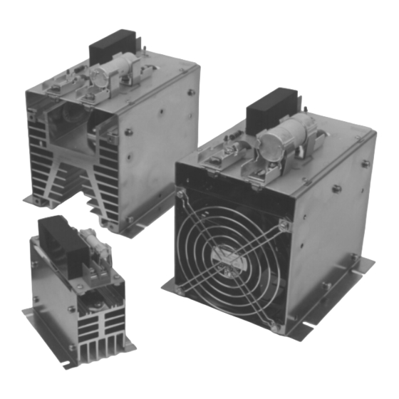
Page 2: Description
TC210 Instructional Manual Powtier Controls Limited DESCRIPTION The MAXIWAT TC210 range of thyristor switching capacities of 16A, 25A, 40A, 55A, 75A, 100A, 125A units, combine high power capability with compact and 155A. Each assembly is fully isolated and dimensions. With the emphasis on safety and incorporates high speed fuse, excess voltage reliability, the units are ruggedly housed. -
Page 3: Installation
Powtier Controls Limited TC210 Instructional Manual Tactical Controls Limited TC210 Instructional Manual INSTALLATION Under normal operating conditions it is important Table 1. Fuses and fuse ratings for the TC210 that the TC210 power switching unit should be MAXIWAT range. mounted VERTICALLY (as shown in figure 3), with the FAN end facing DOWNWARDS if fitted. - Page 4 TC210 Instructional Manual Powtier Controls Limited Figure 1a. Single phase 16 to 25A wiring. Figure 1b. Single phase 40 to 55A wiring. 20 June 1996 - 4 - 210IM Issue 2.1...
- Page 5 Powtier Controls Limited TC210 Instructional Manual Figure 1c. Single phase 75 to 155A wiring. Figure 1d. Single phase line to neutral connection Figure 1e. Single phase line to line connection 210IM - 5 - 20 June 1996 Issue 2.1...
-
Page 6: Diagnostic Aid - Leds
TC210 Instructional Manual Powtier Controls Limited DIAGNOSTIC AID - LEDs The light emitting diode, LED 1 near to the input terminals is used to indicate the input status. When the input is 0V, LED 1 is `OFF' and when the input is greater than 5Vdc, LED 1 is `ON'. -
Page 7: Specification
Powtier Controls Limited TC210 Instructional Manual TECHNICAL SPECIFICATION OUTPUT INPUT Supply voltage 100 to 660 Vrms Logic (+10 -15%) 5 - 30 Vdc Current rating 16 to 155 A. Must operate at >4.5 Vdc Input/Output isolation 2500 Vrms. Must release at <1.5 Vdc... -
Page 8: Dimensions
TC210 Instructional Manual Powtier Controls Limited Figure 3. Dimensions. DIMENSIONS Current Width Height Depth Fixing Fixing Fixing rating "W" "H" "D" centre"A" centre"B" holes"C" 16-25A 40-55A 100-155A All dimensions are in mm. 1. Due to the fan, the overall height is increased by 40 mm. - Page 9 Powtier Controls Limited TC210 Instructional Manual TC210-25A with soft-start wiring diagram. 210IM - 9 - 20 June 1996 Issue 2.1...
Need help?
Do you have a question about the MAXIWAT TC210 Series and is the answer not in the manual?
Questions and answers