Table of Contents
Advertisement
Available languages
Available languages
Quick Links
Anschluss- und Bedienungsanleitung
Niveauregelung für leitfähige Flüssigkeiten
24 V Ausführung ohne Gehäuse
Technische Änderungen vorbehalten
0141 0316-152
13.05.2016
B+B Thermo-Technik GmbH | Heinrich-Hertz-Straße 4 | D-78166 Donaueschingen
Fon +49 771 83160 | Fax +49 771 8316-50 | info@bb-sensors.com | bb-sensors.com
Leistungsmerkmale
•
Niveauregler für leitfähige Flüssigkeiten
•
Überwacht gleichzeitig 4 Niveaus
•
Zwei unabhängige Stufen für Füllen / Entleeren
•
Zwei leistungsstarke, potentialfreie Relais mit Wechselkontakt
•
Betriebsspannung 24 V AC/DC
1 / 9
Advertisement
Chapters
Table of Contents

Subscribe to Our Youtube Channel
Related Manuals for B+B Sensors WLSW-24V


Summary of Contents for B+B Sensors WLSW-24V
- Page 1 Anschluss- und Bedienungsanleitung Niveauregelung für leitfähige Flüssigkeiten 24 V Ausführung ohne Gehäuse Leistungsmerkmale • Niveauregler für leitfähige Flüssigkeiten • Überwacht gleichzeitig 4 Niveaus • Zwei unabhängige Stufen für Füllen / Entleeren • Zwei leistungsstarke, potentialfreie Relais mit Wechselkontakt • Betriebsspannung 24 V AC/DC Technische Änderungen vorbehalten B+B Thermo-Technik GmbH | Heinrich-Hertz-Straße 4 | D-78166 Donaueschingen 1 / 9...
-
Page 2: Table Of Contents
Anschluss- und Bedienungsanleitung Niveauregelung für leitfähige Flüssigkeiten 24 V Ausführung ohne Gehäuse Allgemeine Gefahren- und Warnhinweise Hinweise zur Dokumentation Sicherheitshinweise Beschreibung Funktionsweise Ablaufdiagramm Lieferumfang Technische Daten Bestelldaten Montage, Einstellung und Konfiguration Elektrischer Anschluss 5.1.1 Sicherheitshinweise 5.1.2 Betriebsspannung 5.1.3 Lastkreis Einstellung der Schaltpunkte 5.3 Konfiguration der Betriebsart Anschluss eigener Fühler 5.4.1... -
Page 3: Allgemeine Gefahren- Und Warnhinweise
Anschluss- und Bedienungsanleitung Niveauregelung für leitfähige Flüssigkeiten 24 V Ausführung ohne Gehäuse Allgemeine Gefahren- und Warnhinweise Hinweise zur Dokumentation Bitte lesen Sie unbedingt die folgenden Hinweise vor der Inbetriebnahme! Die in der Betriebsanleitung verwendeten Symbole sollen auf Sicherheitsrisiken aufmerksam machen. Das jeweils verwendete Symbol kann den Text des Sicherheitshinweises nicht ersetzen. Der Text ist daher immer vollständig zu lesen! Dieses Symbol weist darauf hin, dass mit Gefahren für Personen, Material oder Umwelt zu rechnen ist. -
Page 4: Ablaufdiagramm
Anschluss- und Bedienungsanleitung Niveauregelung für leitfähige Flüssigkeiten 24 V Ausführung ohne Gehäuse Im Flüssigkeitsbehälter werden vier Elektroden (E1..E4) montiert, die entsprechend dem gewünschten Schaltpunkt in das Medium ragen. Eine fünfte Elektrode am Behälterboden (nicht skizziert) dient als Bezugselektrode. Entsprechend dem Wasserkontakt wird der Füllstand mit vier grünen LED´s L1 bis L4 angezeigt. Bei vollständig leerem Behälter er- scheint die rote LED. -
Page 5: Lieferumfang
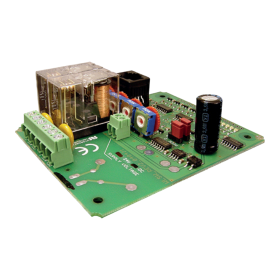
Die Lieferung der 24 V Ausführung erfolgt als Modul (Platine) 95 x 75 mm ohne Gehäuse und ohne Bedienteil. Technische Daten Allgemein 22 V...28 V DC 45 mA max. Betriebsspannung Typ-MOD24V (WLSW-24V) 15 V...25 V AC 60 mA max. Relais Wechselkontakt für ohmsche Last Belastbarkeit Schließer 230 V AC / 5 A... -
Page 6: Betriebsspannung
Anschluss- und Bedienungsanleitung Niveauregelung für leitfähige Flüssigkeiten 24 V Ausführung ohne Gehäuse 5.1.2 Betriebsspannung Der Anschluss der Betriebsspannung erfolgt an den Klemmen „SUPPLY VOLTAGE“. Die Höhe der Nenn-Betriebsspannung ist auf der Platine sowie auf dem Relais angegeben und muss ent- sprechend den Angaben im Datenblatt eingehalten werden, um einwandfreie Funktion zu gewährleisten. -
Page 7: Einstellung Der Schaltpunkte
Anschluss- und Bedienungsanleitung Niveauregelung für leitfähige Flüssigkeiten 24 V Ausführung ohne Gehäuse Einstellung der Schaltpunkte Die Justage des Schaltpunktes erfolgt je nach Leitfähigkeit des Wassers an den Trimmpotentiometern. In der Regel reicht es für die meisten Anwendungen mit sauberem Regen- oder Leitungswasser aus, die Poten- tiometer in die empfindlichste Stellung (Rechtsanschlag) einzustellen, was einem Schaltpunkt von ca. -
Page 8: Belegung Der Eingangsbuchse (Rj12)
Anschluss- und Bedienungsanleitung Niveauregelung für leitfähige Flüssigkeiten 24 V Ausführung ohne Gehäuse 5.4.1 Belegung der Eingangsbuchse (RJ12) Stift Funktion Farbe (Kabel 6-polig) Beschreibung Weiss 15 V Braun Level 4 (E4), oben Grün Level 3 (E3) Gelb Level 2 (E2) Grau Level 1 (E1), Boden Rosa Bezugselektrode... -
Page 9: Garantie
Anschluss- und Bedienungsanleitung Niveauregelung für leitfähige Flüssigkeiten 24 V Ausführung ohne Gehäuse • Ideal geeignet sind Stabelektroden aus Edelstahl, die von oben in das Medium ragen. Die Bezugselektrode ist in der Mitte der vier diagonal angeordneten Messelektroden platziert, im Abstand von ca. 1-5 cm. Der Abstand muss so groß gewählt werden, dass durch die Oberflächenspannung keine Tropfen an den Stäben zurück bleiben können, falls der Pegel sinkt. Derartige Elektroden sind praktisch wartungsfrei •... - Page 10 Connection and operation manual Level controller for conducting liquids 24 V OEM-version without housing Features • Level controller for conducting liquids • Simultaneous monitoring of 4 levels • Two independent circuits for fill/empty • Two high rating potential free relays with NO/NC contacts •...
- Page 11 Connection and operation manual Level controller for conducting liquids 24 V OEM-version without housing General dangers and precautions Instructions regarding documentation Safety instructions Description Functional description Operating sequence diagram Scope of supply Technical data Ordering information Assembly, adjustment and configuration Electrical connection 5.1.1 Safety instructions...
-
Page 12: General Dangers And Precautions
Connection and operation manual Level controller for conducting liquids 24 V OEM-version without housing General dangers and precautions Instructions regarding documentation Please carefully read the following instructions before putting into operation! The symbols used in the operating manual are to make you careful, before hand, regarding safety considerations and dangers. -
Page 13: Operating Sequence Diagram
Connection and operation manual Level controller for conducting liquids 24 V OEM-version without housing In liquid reservoir, four electrodes (E1..E4) are mounted in the medium, at heights corresponding to the required switching point. A fifth electrode is placed at the bottom of the reservoir (not shown in sketch) which works as the reference electrode. According to water contact, the fill level is indicated through 4 green LED´s L1 to L4. -
Page 14: Scope Of Supply
Ordering information Switching device and accessories Ordering No. Level controller-PCB, for 12 V DC WLSW-12V Level controller-PCB, for 24 V DC WLSW-24V Level controller 230 V, in housing with control unit WLS-GEH230 Housing ET210F 0209 0018-01 Control unit with accessories... -
Page 15: Operating Voltage
Connection and operation manual Level controller for conducting liquids 24 V OEM-version without housing 5.1.2 Operating voltage The operating voltage is connected at the terminals “SUPPLY VOL- TAGE“. The rating of nominal voltage is mentioned on the PCB and also on the relay and must be maintained as per specifications on the data sheet in order to ensure an error free functioning. -
Page 16: Switching Point Adjustment
Connection and operation manual Level controller for conducting liquids 24 V OEM-version without housing Switching point adjustment The switching point is adjusted as per conductivity of wa- ter with the preset potentio-meters. In normal practice, it is good enough to set the potentiometer in the most sensitive position (right side limit). -
Page 17: Pin Configuration Of Input Socket (Rj12)
Connection and operation manual Level controller for conducting liquids 24 V OEM-version without housing 5.4.1 Pin configuration of input socket (RJ12) Function Colour (6 core cable ) Description White 15 V Brown Level 4 (E4), highest Green Level 3 (E3) Yellow Level 2 (E2) Grey... -
Page 18: Guarantee
Connection and operation manual Level controller for conducting liquids 24 V OEM-version without housing Guarantee Hearty congratulations on the purchase of this high quality product! The quality of our products is constantly monitored within the frame- work of our Quality Management systems as per ISO 9001 standards. Nevertheless, if still there are any reasons for complaint, we are ready to rectify the shortcomings free of charge within the guarantee period of 24 months, if it is evident that the defect is due to some mistake on our part.
Need help?
Do you have a question about the WLSW-24V and is the answer not in the manual?
Questions and answers