Table of Contents
Advertisement
Quick Links
Advertisement
Table of Contents

Related Manuals for akira LCT-32EL0SSTP


Summary of Contents for akira LCT-32EL0SSTP
- Page 1 LCD TV Service Manual...
- Page 2 - 2 - MODEL: LCT-32EL0SSTP Model No.: LCT-32ELOSSTP.doc Version: 1.0...
-
Page 3: Table Of Contents
- 3 - CONTENTS SAFETY PRECAUTION......................... 4 SPECIFICATION............................. 6 DISPLAY OVERVIEW.......................... 10 ADJUSTMENT STANDARD........................ 12 FIRMWARE UPDATE........................... 15 FACTORY MENU ..........................18 TROUBLESHOOTING ......................... 19 BLOCK DIAGRAM ..........................22 BILL OF MATERIAL ..........................24 CIRCUIT DIAGRAM ..........................37 EXPLODED VIEW AND PART LIST ....................46 WALL-MOUNTING BRACKET INSTALLATION GUIDE .............. -
Page 4: Safety Precaution
- 4 - IMPORTANT SAFETY PRECAUTION Model No.: LCT-32ELOSSTP.doc Version: 1.0... - Page 5 - 5 - Model No.: LCT-32ELOSSTP.doc Version: 1.0...
-
Page 6: Specification
SPECIFICATION Panel Type 32” Wide TFT Colour LCD Display Area 697.685mm * 392.256mm Display Color (8bit) 16.7 million Pixel Pitch 170.25um * 510.75um * RGB Panel Recommended Resolution 1366 * 768 Contrast Ratio 500(Min), 600(Typ) Luminance white 500 cd/㎡ Viewing angle free (R/L 176(Typ.), U/D Viewing Angle 176 (Typ.) Analog RGB 15 pin D-Sub Input... - Page 7 Gross:24.6kg Remote Controller 932(W)*238(D)*567(H) : Speaker(stand Dimension included) Specification are subject to changes without prior notice. Model No.: LCT-32ELOSSTP.doc Version: 1.0...
- Page 8 Chassis General Spec Model No.: LCT-32ELOSSTP.doc Version: 1.0...
- Page 9 Model No.: LCT-32ELOSSTP.doc Version: 1.0...
-
Page 10: Display Overview
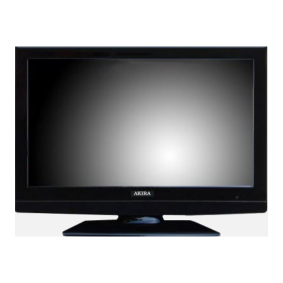
DISPLAY OVERVIEW – Front View 1) LCD Display : Displays the current contents of the display. 2) MENU Button : Displays the main OSD menu. Exitx from a sub-menu. 3) SOURCE Button : Displays a menu of all of the available input sources. 4) Channel(▼/▲) Buttons : Press CH(▲) or CH(▼) to change channels. - Page 11 Rear View 1) DVI-D : Connects the DVI cable to the Dvi connector on the computer. 2) ANALOG RGB : Connects the VGA signal cable to the VGA connector on the computer. 3) PC AUDIO INPUT : Connect to the audio-output port of a PC. 4) Head Phone Jack : Connects with a headphone.
-
Page 12: Adjustment Standard
ADJUSTMENT STANDARD APPLICATION This standard is applied on all LCD TV models with VCB3001 and VCB3002 Chassis. ASSIGNMENT This chassis is a non-charging type with insulated power unit. Therefore, insulated transformer is not required. In order to protect the adjustment unit, however, it is recommended that an insulated transformer between the power supply line and input side of chassis is to be operated and adjusted. - Page 13 b) Analog EDID DATA (RGB) c) Digital EDID DATA (DVI) 2. AD9883A-Set Adjustment Introduction Analog Adjustment for AD9883A-Set => This is a function for the optimal level of black and gain to be automatically set from digital converter and RGB variation to be adjusted. Used Equipment Pattern Generator(capable of generating 720P Vertical 100% Color Bar Pattern (The pattern type is shown as follows and the caution should be used not to...
- Page 14 <Figure> Adjustment Pattern : 720P Vertical Color Bar> 3. Adjustment Method Input 100% Vertical Color Bar Pattern (TVBAR_100) in 720P Mode which may be supported for Component input, and then select Component1 or Component2 for input and “STANDARD” for image. Wait for more than a second after receiving signal and press S.SELECT on adjustment R/C (Service remote controller) while selecting “WB Adjust”...
-
Page 15: Firmware Update
FIRMWARE UPDATE Model No.: LCT-32ELOSSTP.doc Version: 1.0... - Page 16 Model No.: LCT-32ELOSSTP.doc Version: 1.0...
- Page 17 Model No.: LCT-32ELOSSTP.doc Version: 1.0...
-
Page 18: Factory Menu
FACTORY MENU Model No.: LCT-32ELOSSTP.doc Version: 1.0... -
Page 19: Troubleshooting
TROUBLESHOOTING Power Related Model No.: LCT-32ELOSSTP.doc Version: 1.0... - Page 20 Screen Related Model No.: LCT-32ELOSSTP.doc Version: 1.0...
- Page 21 Sound Related Model No.: LCT-32ELOSSTP.doc Version: 1.0...
-
Page 22: Block Diagram
BLOCK DIAGRAM – Main Board Model No.: LCT-32ELOSSTP.doc Version: 1.0... - Page 23 Power Board Model No.: LCT-32ELOSSTP.doc Version: 1.0...
-
Page 24: Bill Of Material
B.O.M Location Number Item Desc. Item Spec. PWB(PCB) ASSY,MAIN VCB4100 MAIN TOTAL PWB(PCB) ASSY,MAIN VCB4100 MAIN HAND INSERTING BOARD LABEL VCB4100 JACK AUDIO PHONE JACK 3.5PIE NINENEW SJ3501-5 H7 AV-JACK J/B 9P + DIN (RCA/Mini-Din D-SUB 15F- BLUE DSH03A-15F-BU 15P D-SUB 2.29MM FEMALE RIGHT ANGLE CONNECTOR(CA-29DVI-A-2) 29P DVI-I CIRCUIT RIGHT ANGLE ( SCART JACK... - Page 25 Al. CAPCITOR/SAMYOUNG 22UF 50V M 5*11*2.5 SHL-TYPE C359 Al. CAPCITOR/SAMYOUNG 4.7UF 50V M 5*11*2.5 SHL-TYPE C405 Al. CAPCITOR/SAMYOUNG 3.3UF 50V M 5*11*2.5 SHL-TYPE C367 Al. CAPCITOR/SAMYOUNG 10UF 16V M 5*11*2.5 SHL-TYPE C161 C162 C167 C168 IC,EON FLASH ROM EN29LV004A-70 PLCC32P MICOM LABEL VCB4200 IC, MYSON...
- Page 26 C426 C432 C433 C439 C446 C451 C454 C455 C465 C466 C481 C482 C483 C487 C488 C491 C492 C494 C497 C498 C501 C502 C504 C514 CAPACITOR, CHIP CERAMIC 15PF 50V J NP0 1608 R/TP CAPACITOR, CHIP CERAMIC 12PF 50V J NP0 1608 R/TP C414 C419 C477...
- Page 27 CHIP RESISTOR 1.8K 1/10W J 1608 D.R/TP R555 R108 R119 R120 R122 CHIP RESISTOR 10K 1/10W J 1608 D.R/TP R145 R170 R173 R179 R216 R221 R237 R239 R243 R591 R592 R594 R597 R617 R619 R651 CHIP RESISTOR 100 1/10W J 1608 D.R/TP R176 R257 R258...
- Page 28 CHIP RESISTOR 3.3K 1/10W J 1608 D.R/TP R599 CHIP RESISTOR 22K 1/10W J 1608 D.R/TP CHIP RESISTOR 47K 1/10W J 1608 D.R/TP R551 R552 R246 R247 R252 R253 R454 R472 R476 R478 R479 R480 R490 R491 R492 R605 R606 R607 R626 R627 R628...
- Page 29 CHIP BEAD HB-1H1608-300 CERATEC 1608MM R/TP CHIP BEAD HH-1M2012-121 CERATEC 2012MM R/TP R574 R579 R589 R690 CHIP INDUCTOR FI-B2012-332-KJT 3.3UHCERATEC 2012MM R/TP CHIP INDUCTOR FI-B2012-103-KJT 10UH CERATEC2012MM R/TP CHIP INDUCTOR FI-B2012-561-KJT 0.56UH CERATEC2012MM R/TP IC,INTERGRAL REGULATOR 1.0A 1.8V IL-1117-18 IC,INTERGRAL REGULATOR 1.0A 2.5V IL-1117-25 IC,INTERGRAL REGULATOR 1.0A 5.0V IL-1117-50...
- Page 30 CRISTAL SX-1 SMS, 14.318MHZ CL 18PF CRISTAL SX-1 SMS, 20.250MHZ CL 18PF CRISTAL SX-1 SMS, 12.000MHZ CL 20PF K6R4008V1D 512Kx8 Bit High Speed Static RAM(3.3V Operating). IC, TEXAS INSTRUMENT 10W STEREO AUDIO POWER AMPLIFIER TPA3004 QFP48P IC, TEXAS INSTRUMENT TPA6110A2 SOP-8P 150mW STEREO AUDIO POWER AMPLIFIER IC, PHILIPS 74LVC/LVT14ADR2 14P,SOIC TP LEVE IC, PHILIPS...
- Page 31 CIRCUIT DIAGRAM Model No.: LCT-32ELOSSTP.doc Version: 1.0...
- Page 32 Model No.: LCT-32ELOSSTP.doc Version: 1.0...
- Page 33 Model No.: LCT-32ELOSSTP.doc Version: 1.0...
- Page 34 Model No.: LCT-32ELOSSTP.doc Version: 1.0...
- Page 35 Model No.: LCT-32ELOSSTP.doc Version: 1.0...
- Page 36 Model No.: LCT-32ELOSSTP.doc Version: 1.0...
-
Page 37: Circuit Diagram
Model No.: LCT-32ELOSSTP.doc Version: 1.0... - Page 38 Model No.: LCT-32ELOSSTP.doc Version: 1.0...
- Page 39 PCB – Top Silk Model No.: LCT-32ELOSSTP.doc Version: 1.0...
- Page 40 PCB- Bottom Silk Model No.: LCT-32ELOSSTP.doc Version: 1.0...
- Page 41 PCB - Bottom Solder Model No.: LCT-32ELOSSTP.doc Version: 1.0...
- Page 42 Model No.: LCT-32ELOSSTP.doc Version: 1.0...
- Page 43 Model No.: LCT-32ELOSSTP.doc Version: 1.0...
- Page 44 Model No.: LCT-32ELOSSTP.doc Version: 1.0...
- Page 45 Model No.: LCT-32ELOSSTP.doc Version: 1.0...
-
Page 46: Exploded View And Part List
EXPLODED VIEW Model No.: LCT-32ELOSSTP.doc Version: 1.0... -
Page 47: Wall-Mounting Bracket Installation Guide
WALL-MOUNTING BRACKET INSTALLATION GUIDE READ CAREFULLY BEFORE INSTALLATION! THE INSTALLATION GUIDE SHOULD BE RETAINED FOR FUTURE REFERENCE. Caution: 1. Do NOT attempt to install the TV by yourself to avoid mistakes or hazard. Refer all installation to qualified servicing personnel. 2.
Need help?
Do you have a question about the LCT-32EL0SSTP and is the answer not in the manual?
Questions and answers