Table of Contents
Advertisement
Quick Links
INSTALLATION AND MAINTENANCE INSTRUCTIONS
MMF-302-6 Six Zone Interface Module
SPECIFICATIONS
Normal Operating Voltage:
Stand-By Current:
Alarm Current:
Temperature Range:
Humidity:
Dimensions:
Accessories:
Wire Gauge:
Maximum IDC Wiring Resistance:
External Power Supply Voltage:
Ripple Voltage:
IDC (supervised and power limited)
DC Voltage:
Frequency:
Alarm Current:
Standby Current 6 circuits:
BEFORE INSTALLING
This information is included as a quick reference installation guide. Refer to
the appropriate Fire•Lite control panel installation manual for detailed sys-
tem information. If the modules will be installed in an existing operational
system, inform the operator and local authority that the system will be tempo-
rarily out of service. Disconnect the power to the control panel before install-
ing the modules. This system contains static sensitive components. Always
ground yourself with a proper wrist strap before handling any circuits so that
static charges are removed from the body. The module housing should also
be grounded.
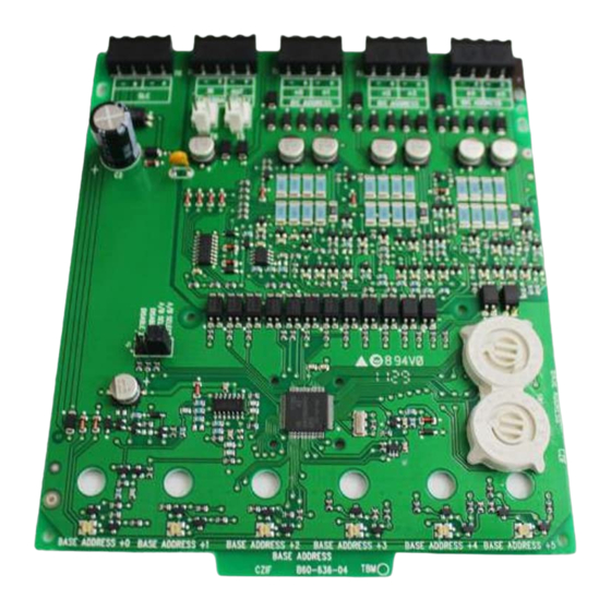
GENERAL DESCRIPTION
The MMF-302-6 Six Zone Interface Module is intended for use in an intelli-
gent alarm system. Each module provides an interface between the intelligent
alarm system and a conventional alarm system loop. A common SLC input is
used for all modules, and the initiating device loops share a common super-
visory supply and ground. Otherwise, each monitor operates independently
from the others. Each module has its own unique address.
A pair of rotary code switches is used to set the address of the first module
from 01 to 154. The remaining modules are automatically assigned to the next
five higher addresses. Provisions are included for disabling a maximum of two
unused modules to release the addresses to be used elsewhere. Each mod-
ule also has panel controlled bicolor LED indicators. The panel can cause the
LEDs to blink, latch on, or latch off.
A list of compatible two-wire System Sensor Smoke detectors for use with the
MMF-302-6 is available on the System Sensor website at systemsensor.com.
Included:
(5) 1 x 4 Terminal Blocks
(2) 1.25" Stand offs
(4) Machine Screws (2) Nuts
(6) 3.9k Ohm End of Line Resistors
Shipped on Board:
(2) Shunts in Class A/B position
(Shipped in Class B position, remove shunts for Class A)
15-32 VDC
2.3 mA @ 24 V
40 mA (assumes all six LEDs solid on)
32°F to 120°F (0°C to 49°C)
10 to 93% Non-condensing
6.8˝H x 5.8˝W x 1.25˝D
CH-6 Chassis; BB-6F Cabinet; BB-2F Cabinet
12-18 AWG
25 Ohms
Regulated 24 VDC
0.1 volts RMS maximum
18-28 volts power limited
DC
90mA per circuit
42mA Maximum @18 VDC
56mA Maximum @24 VDC
66mA Maximum @28 VDC
(3) Shunts
(1) Long Power Supply Jumper
NOTICE: This manual should be left with the owner/user of the equipment.
COMPONENTS
Following are descriptions of the MMF-302-6 mounting frameworks. There are
two mounting options for MMF-302-6 modules:
• Up to six MMF-302-6 modules can be installed on a CH-6 in a BB-6F
cabinet
• One or two MMF-302-6 modules can be installed in a BB-2F cabinet
Chassis
The CH-6 chassis is used to mount MMF-302-6 modules in a BB-6F cabinet.
It accommodates up to six MMF-302-6 modules in a single cabinet row three
modules wide and two modules deep.
FIGURE 1. CH-6 CHASSIS
The BB-2F cabinet has a built-in chassis that will accommodate one or two
MMF-302-6 modules.
FIGURE 2. BB-2F CABINET
The front MMF-302-6 module positions of each chassis are offset below the
rear MMF-302-6 module positions so that all of the status indicators are visible.
Cabinets
A BB-6F will house the CH-6 chassis with up to six MMF-302-6 modules in-
C0202-00
stalled on it. Refer to cabinet installation documents for dimensions.
1
One FireLite Place
Northford, CT 06472
Phone: 203.484.7161
C0206-00
C0234-00
I56-1900-023
7/1/2022
Advertisement
Table of Contents

Summary of Contents for Fire-Lite Alarms Honeywell MMF-302-6
- Page 1 INSTALLATION AND MAINTENANCE INSTRUCTIONS One FireLite Place MMF-302-6 Six Zone Interface Module Northford, CT 06472 Phone: 203.484.7161 SPECIFICATIONS Normal Operating Voltage: 15-32 VDC Stand-By Current: 2.3 mA @ 24 V Alarm Current: 40 mA (assumes all six LEDs solid on) Temperature Range: 32°F to 120°F (0°C to 49°C) Humidity:...
- Page 2 The BB-2F cabinet houses one or two MMF-302-6 modules on the internal The steps in Figures 6a and 6b describe and illustrate module installation chassis that is part of the cabinet. Refer to cabinet installation documents for when the rear chassis position and the position in front of it will be filled. dimensions.
- Page 3 WIRING NOTES A shunt is provided to disable a maximum of • Power-limited circuits must employ type FPL, FPLR, or FPLP cable as two unused modules in Class B operation and required by Article 760 of the NEC. Class A operation. Modules are disabled from the highest address and work downward.
- Page 4 FIGURE 10. EXAMPLE OF MULTIPLE BOARDS SHARING SAME EXTERNAL SUPPLY Refer to figures 8 and 9 for typical wiring. Make certain lip on long power supply jumper engages retaining tab on T5 or T6 as shown in View A-A. PCB 1 PCB 2 —...
Need help?
Do you have a question about the Honeywell MMF-302-6 and is the answer not in the manual?
Questions and answers